
EXECUTIVE SUMMARY:
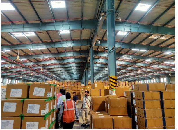
Non Destructive Technique of Warehouse Flooring at STAR TRACK TERMINALS LTD, DADRI MAIN RD, TILAPTA VILLAGE, GREATER NOIDA, UTTAR PRADESH 201306
Duration of Testing:-08/07/2022
Table 1
| NON DESTRUCTIVE AND SEMI-DESTRUCTIVE TEST SUMMARY | ||||
| S.NO | TEST NAME | REFERENCE OF TEST | PURPOSE OF TEST ,TEST RESULT & COMMENT | REFERENCE |
| 1 | Rebound Hammer Test | IS 13311 (Part-2)- 1992, ASTM C 805-02, BS 6089:1981 and BS 1881: Part 202, BSEN:13791 | To determining the estimated compressive strength and uniformity of concrete Around 6 test conducted on RCC Flooring and compressive strength of concrete tested range from M20-M24 Grade of concrete Which is Greater than M20 as per the latest codal provision of IS 456:2000 | Table-5 |
| 2 | Ultrasonic Pulse Velocity | IS 13311 (Part-1)- 1992, ASTM: C597-83, BS 6089: 1981 and BS 1881: Part 203 and BSEN:13791 | To determine the quality of concrete, soundness and density of concrete. Around 6 test conducted on RCC Flooring its quality is found to be Good-Excellent Concrete. Which clearly indicates that there is no presence of voids/minor cracks inside the concrete | Table-5 |
| 3 | pH value | 3 Samples are taken from the floor and found to be in base zone. Which indicate the floor has capacity to resist the concrete rusting | Table-8 |
FINAL CONCLUSION:-
From the Rebound Hammer tests, it is clear that the strength of concrete is in the range of M20 to M24. As per USPV test results, it is found that mostly concrete is of Good -Excellent category and there is no presence of cracks at various locations. As per the pH test the concrete was found to be in base zone.
Summary of Floor Analysis
Based on the output from non destructive testing the maximum load carrying capacity of the existing floor was 9 tonnes.
Require strength of flooring as per mezzanine floor 38 tonnes. Hence we recommend to use isolated footing for mezzanine floor.
- INTRODUCTION:
- Site-The existing warehouse structure at DADRI MAIN RD, TILAPTA VILLAGE, GREATER NOIDA, UTTAR PRADESH 201306 requested to M/s OB DEVELOPERS (STRUCTURAL AUDIT
AGENCY)for Condition Assessment of flooring through conditions survey using Non-destructive testing.
- Selection of tests:
Tests are selected on the basis of the requirements of the overall objectives of the investigation and the observations made during a quick walk over survey. In this investigation, following in-situ and laboratory tests were considered necessary for achieving the overall objectives stated earlier for the structure. Various Test were Conducted for the evaluation of the Structure:
The various Non-Destructive Tests proposed to be carried out for condition survey of the structure are listed below:
- Ultrasonic Pulse Velocity Test as per IS: 13311 (Part-1)-1992 for ascertaining the quality of concrete, soundness and density of concrete.
- Rebound Hammer Test: For determining the estimated compressive strength of concrete and uniformity of concrete in terms of surface hardness as per IS 13311 (Part-2)-1992.
- Sample and Site Data Collection:-
The four instruments i.e. Ultrasonic Pulse velocity meter, Rebound Hammer, Half-Cell Potential meter & Cover Meter were used to collect the data from the structure .Carbonation test has been done on extracted concrete core sample as well as through the drilling the concrete surface test locations were selected after visual survey and data was collected from below mentioned test locations in the structure. As per surface condition required numbers of tests on different concrete surface have been decided to get the overall
idea of concrete quality.
- Table 4-Number Of Tests To Be Conducted:-
| SN | Location | Rebound Hammer Test | Ultrasonic Pulse Velocity Test | Ph Value |
| 1 | Grid No.-18 Center | 1 | 1 | 1 |
| 2 | Grid No.-16 Center | 1 | 1 | |
| 3 | Grid No.-12 Right | 1 | 1 | |
| 4 | Grid No.-10 Right | 1 | 1 | 1 |
| 5 | Grid No.-8 Left | 1 | 1 | |
| 6 | Grid No.-2 Left | 1 | 1 | 1 |
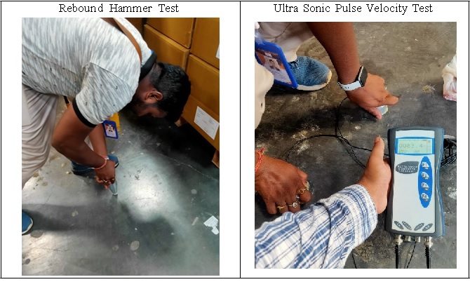
2.1.1 REBOUND HAMMER TEST:-
Purpose:-
This test gives a measure of the surface hardness of the concrete surface. Although there is no direct relationship between this measurement of surface hardness and strength, an empirical relationship exists. Rebound hammer is the best known methods of comparing the concrete in different parts of a structure and indirectly assessing concrete strength. The rebound hammer should be considered as a means of assessing variations of strength within a structure rather than an accurate means of assessing the strength. Objective of testing:-
Rebound hammer test is performed to determine the following:
- Surface hardness
- Uniformity of concrete over the structure
- Grade of concrete
- Estimated strength which is derived from establishing a relationship between in-situ core strength and rebound number.
- Uniformity of concrete over the structure
References:-
BS 6089:1981 and BS 1881:Part 202,
IS13311(Part2):1992
ASTM C 805-02
Influencing factors:-
Rebound hammer test results are considerably influenced by these factors:
- Size, shape and rigidity of the specimen
- Age of test specimen
- Smoothness of surface and internal moisture condition of the concrete
- Carbonation of concrete surface
- Age of test specimen
Testing Method:-
According to ASTM C 805-02 clause 7.1 the concrete members to be tested shall be at least 100mm thick and fixed within a structure. Towelled surfaces generally exhibit high rebound numbers than screed or formed finishes. Do not compare the test results if the form material against which the concrete is placed is not similar.
Heavily textured, soft or surfaces with loose mortar shall be ground flat with abrasive stone. Smooth formed or towelled surfaces do not have to be ground prior to testing.
Also this test is not conducted directly over the reinforcing bars having cover less than 20mm. The surface under test should be clean and smooth because rough surfaces cannot be tested as they do not give reliable results. Dirt or other loose material on the surface can be removed using a grinding stone prior to test.
ULTRASONIC PULSE VELOCITY:-
Purpose:-
Although there is no fundamental relationship between pulse velocity and strength, an estimation of strength can be obtained by correlation. The method has perhaps a greater potential for comparing known sound concrete with affected concrete.
Ultrasonic pulse velocity is a means of assessing variations in the apparent strength of concrete.
The quality gradation of concrete can be appraised at best qualitatively as `excellent’, `good’, `medium’ or
`doubtful’. The meanings of the term `excellent’, `good’, `medium’ and `doubtful’ are based on ultra-sonic pulse velocity measured at site and are as per the nomenclature of IS 13311(part-1): 1992. To strike balance between the reliability, speed and damage to structure, core test have to be used to establish a correlation between rebound number index and the estimated in-situ strength with the USPV test results in the investigation.
Objective of testing:-
Ultrasonic pulse velocity test is used to establish the following:
- Homogeneity of concrete
- Presence of cracks voids, honeycombing and other imperfections
- Changes in the structure of concrete which may occur with time.
- Quality of one element of concrete in relation to another i.e. comparative quality analysis and gradation of concrete.
- The values of dynamic elastic modulus of the concrete.
- Presence of cracks voids, honeycombing and other imperfections
References:-
BS 6089:1981 and BS 1881:Part203
IS 13311:Part1:1992
ASTM: C597-83.
Influencing factors:-
The velocity of a pulse of ultrasonic energy in concrete is influenced by the stiffness and mechanical strength of the concrete
- Moisture content: The moisture content of the concrete have a small effect in the velocity and can increase the pulse velocity by 2%.
- Surface condition: The testing surface should be smooth any roughness cannot provide reliable readings because of gap between transducers and testing surface.
- Stress: When concrete is subjected to a stress which is abnormally high for a quality of concrete, the pulse velocity may be reduced due to development of micro-cracks.
- Reinforcing bars: The velocity measured in reinforced concrete in the vicinity of reinforcing bars is usually higher than in plain concrete because pulse velocity in steel is 1.2-1.9 times the velocity in plain concrete. Wherever possible, measurements should be made in such a way that steel does not lie in the path of the pulse.
- Surface condition: The testing surface should be smooth any roughness cannot provide reliable readings because of gap between transducers and testing surface.
Testing method:-
According to IS 13311(Part1):1992 clause 5.2 transducers with a frequency of 50 to 60 kHz are useful for most all round applications, and as per IS 13311(Part1):1992 clause 6.2 the path length should be long enough not to be significantly influenced by the heterogeneous nature of concrete. This test requires a flat surface generally only appropriate for unspalled surfaces.
In view of inherent variability in the test results, sufficient number of readings should be taken by dividing the entire structure in suitable grid of markings 30×30 cm or even smaller. Each junction point of the grid becomes a point of observation.
Table Velocity Criterion for Concrete Quality Grading [Ref: IS13311 (part-1)]
| Sr. No. | USPV by Cross Probing (km/sec) | Concrete Quality Grading. |
| 1 | Above 4.5 | Excellent |
| 2 | 3.5 – 4.5 | Good |
| 3 | 3.0 – 3.5 | Medium |
| 4 | Below 3.0 | * Doubtful |
| S. No./Location | Rebound Hammer Test | Ultrasonic Pulse Velocity | ||||||||||||||||
| S.No | Sample Identification/ Location | Hammer Alignme nt | Rebound No. | Avg. Rebou nd No. | Quality Of Concrete | Estimat ed Strengt h (MPa) | Type of surface | Distan ce (mm) | Travel Time (micro sec.) | Av. Velocit y (km/se c) | Direct Proportiona te Velocity (IS, 5.4.1 13311 part 1) | Concret e Quality | ||||||
| WEREHOUSE | ||||||||||||||||||
| 1 | Grid No.- 18 Center | Floor | Vertical Down | 50 | 55 | 56 | 60 | 60 | 54 | 56 | Very Good Layer | 23 | Indirect | 300 | 56.30 | 5.33 | 6.33 | Excelle nt |
| 2 | Grid No.- 16 Center | Floor | Vertical Down | 52 | 56 | 54 | 60 | 60 | 52 | 56 | Very Good Layer | 23 | Indirect | 300 | 46.60 | 6.44 | 7.44 | Excelle nt |
| 3 | Grid No.- 12 Right | Floor | Vertical Down | 55 | 55 | 60 | 55 | 54 | 60 | 57 | Very Good Layer | 24 | Indirect | 300 | 83.40 | 3.60 | 4.60 | Excelle nt |
| 4 | Grid No.- 10 Right | Floor | Vertical Down | 50 | 50 | 54 | 50 | 52 | 54 | 52 | Very Good Layer | 22 | Indirect | 300 | 43.60 | 6.88 | 7.88 | Excelle nt |
| 5 | Grid No.- 8 Left | Floor | Vertical Down | 50 | 54 | 50 | 48 | 50 | 52 | 51 | Very Good Layer | 21 | Indirect | 300 | 116.30 | 2.58 | 3.58 | Good |
| 6 | Grid No.- 2 Left | Floor | Vertical Down | 30 | 48 | 52 | 50 | 54 | 52 | 48 | Very Good Layer | 20 | Indirect | 300 | 114.70 | 2.62 | 3.62 | Good |
- Analysis of uniformity and imperviousness of concrete on the basis of USPV test results:-
The ultrasonic test methodology in concrete is based on the fact that the propagation time expresses the density of the material. It has uniform concrete quality in terms of density. There are indications of air- pockets and voids as significant from USPV test results as per IS:13311 part 1.
Table 6
| Grid No.-18 Center | Excellent |
| Grid No.-16 Center | Excellent |
| Grid No.-12 Right | Excellent |
| Grid No.-10 Right | Excellent |
| Grid No.-8 Left | Good |
| Grid No.-2 Left | Good |
Test was performed under the room temperature varies between 28degree to 32 degree.
- Interpretation of RCC Surface condition, uniformity of concrete and fck value of concrete obtained from Rebound hammer:-
Test results analysis of the Rebound Number values is based on test results conducted over concrete surfaces. Obtained test results explain about pattern of concrete quality of whole structure sections in terms of surface hardness.
Table 7
| Grid No.-18 Center | Very Good Layer |
| Grid No.-16 Center | Very Good Layer |
| Grid No.-12 Right | Very Good Layer |
| Grid No.-10 Right | Very Good Layer |
| Grid No.-8 Left | Very Good Layer |
| Grid No.-2 Left | Very Good Layer |
| NON DESTRUCTIVE TESTING OF DADRI MAIN RD, TILAPTA VILLAGE, GREATER NOIDA, UTTAR PRADESH 201306 | |||
| SL. No. | Sample Identification | pH Value | Remark |
| WEREHOUSE | |||
| 1 | Grid-18 Center | 9.5 | Base Layer |
| 2 | Grid -10 Right | 10.5 | Base Layer |
| 3 | Grid-2 Left | 10 | Base Layer |
| 1 | Footing Size Design | |||
| Load | Pu | 570 KN | ||
| Design Load | P | 380 KN | 38 Tonnes as per PEB | |
| Moment in x dir | Mux | 0 KN-m | ||
| Moment in y dir | Muy | 0 KN-m | ||
| Column size | cx | 300 mm | Considering Base Plate Size | |
| cy | 300 mm | |||
| 2 | Slab Design | |||
| Depth Available at Site | D | 150 mm | ||
| 3 | One Way Shear along x direction | |||
| Vu1 | 147 KN | |||
| ζv | 1.598 MPa | |||
| ζc | 0.263 MPa | |||
| Vc1 | 24 KN |
TESTING PHOTOGRAPHS
Leave a Reply