
Team- OB Developers (Structure Audit Agency)
www.structureauditagency.com
Factors to be analyzed / understood
- Incident loads
- Factors / elements getting affected
- Behavior of affected elements
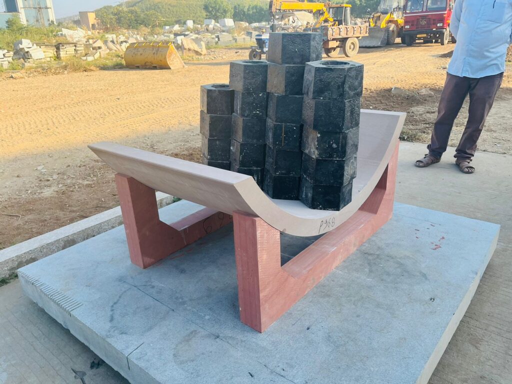
Height of column: 19.363 meters
Diameter of RCC in column: 1200mm
Cladding outer diameter: 1500mm
Thickness of stone for cladding: 70mm
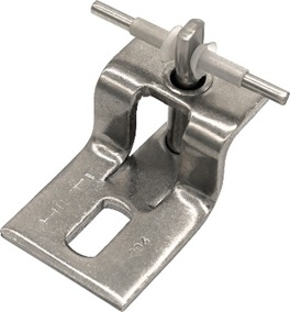
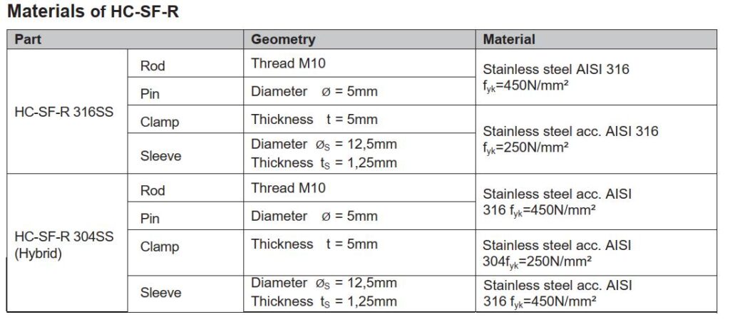
System for cladding: SS sadle / pin (HILTI)-
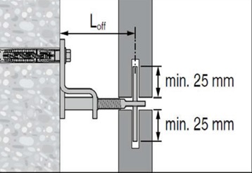
Loff as shown in diagram above is 80mm in project.
- Incident loads, a- dead load
b- wind load
c- load due to seismic movement
Since the columns are internal- NO wind load is expected.
- Dead load – Fasteners and clamps/pins – take load (attached chart in annexure) and are in redundancy.
- In case of a seismic movement – expected lateral movement per each stone
DISPACEMENT CRITERIA FOR CENTRAL FOYER
H = Height of column= 20.675 m
X = displacement difference at top & bottom end
(UNSPEC-X LOAD CASE) = 18 mm – 2 mm = 16 mm X/H = 16 mm/ 20.675 m= 0.78 mm/m
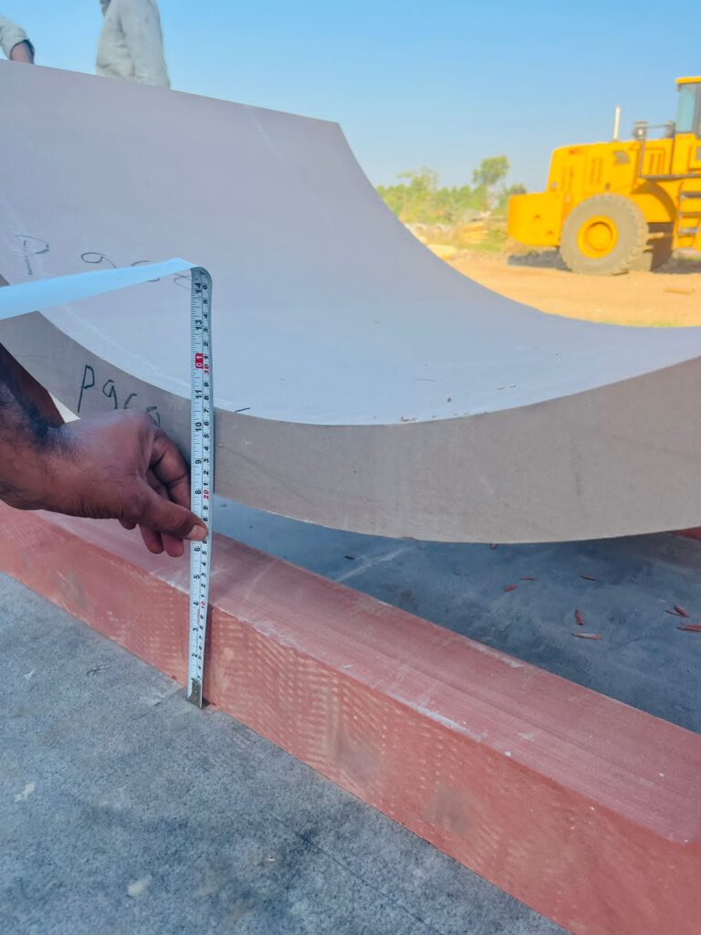
Height of stone cladding piece is 700 mm.
So, X/H per stone cladding piece = 0.78*0.7 = 0.5 mm/stone cladding piece which is differential displacement at top and bottom of each stone cladding of 700 mm high
For design of stone cladding consider (X/H X R) = 0.5 * 4 = 2 mm/ stone cladding piece as differential movement.
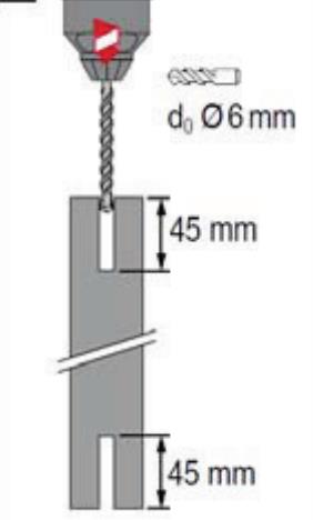
The drill to be used is 6mm , meaning the final dimension after drilling is between 6.5 and 7mm practically. Also site condition may be taken into consideration and that this is a sandstone, hence above 6.5mm.
Pin diameter is at 5mm (given by brand). This give a movement availability of 1.5mm.
Movement capacity upward and downward – drilling is done at 45mm each side (above and below – and the length of the pin is 75 mm, of which 10 mm is lost in the groove. Balance 32-35mm is inside each stone. The empty space above and below is well over 8mm , required for seismic movement may be in the range of 2mm.
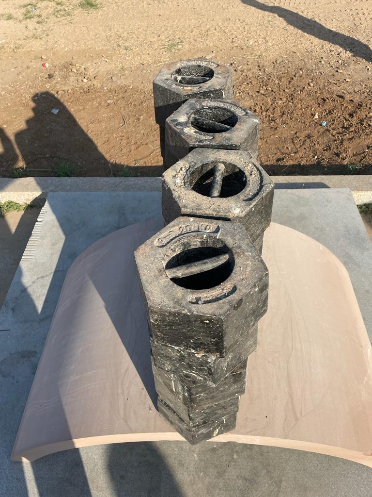
Arrangement with stone-
Fig. b.
View above (fig. b) depicts condition of column stone cladding during seismic movement – total column movement , broken down to individual stone , inter – stone movement calculates at 2mm considering factor of safety. The pic above and Fig. c below depict both axes and results therin.
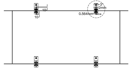
Fig. c – View of movement of stone – pin in seiesmic condition.
Enlarged view – there is an overlap of 0.4mm
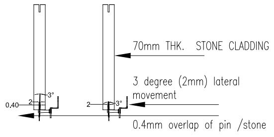
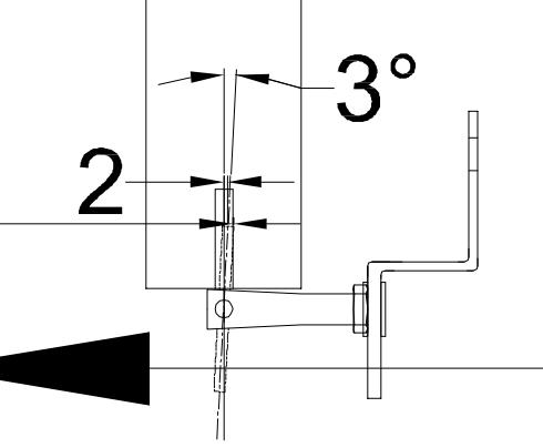
View of the movement of pin – 2mm , in degrees in both axes.
Hence it can be concluded that movement capacity I available to the extent of 1.5mm and the deficit of 0.5mm may be accomodated by using a drill of 8mm which would give us 3mm space availability.
NOW CONSIDERING THE CASE OF THE LATERAL LOAD BEING FULLY APPLIED –
ACCELERATION- SENSITIVE NSE (Non Structural Element) AS PER IS -16700:2017
The design lateral force Fp for the design of acceleration-sensitive NSE’s shall be calculated as:
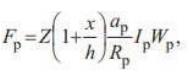
Z = Seismic zone factor = 0.36 (Zone V) Ip = Importance factor of the NSE= 2.5
Considering rigid component with low deformability elements and attachments (Ref. from Table 11-n-3, IS 16700:2017)
Rp = Component response modification factor = 1.5
ap = component amplification factor = 1.0
X = Height of point of attachment of the NSE above top of foundation of bldg. = 27.6 m
H = Overall height of the building = 27.6 m
Wp = Weight of the NSE = 150 kg (weight of each stone as per CPWD)
Fp = 0.36 x (1+ (27.6/27.6)) x (1/1.5) x 2.5 x 150 = 180 kg Bending moment,
L= Height of cladding = 700 mm
M = Fp x distance = WL/4 =180 x 0.7/4 = 31 kg.m
| Minimum Thickness of the Stone Plate to Carry the Pressure. | |||
| S.no | Data of Stone | Value | Unit |
| 1 | Compressive Strength | 90 | N/mm2 |
| 2 | Water Absorption | 1.20% | |
| 3 | Modulus of Rupture | 16 | N/mm2 |
| 4 | Unit Weight of Stone | 24 | Kn/Cum |
| Condition to be Check | |||
| 1 | Moment | 31 | Kg-m |
| 2 | Pressure (w) | 0.48136646 | Kn-m |
| w=Moment/Width of Stone | |||
| 3 | Length of Stone | 1 | m |
| 4 | Width of Stone | 0.644 | m |
| 5 | Safety Factor for Design | 8 | |
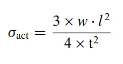
| The Ultimate Strength obtained from the three-point bending test is given by the following equation: | |||
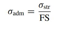 | Equation 1 | ||
| The pressure induced stress at the stone mid span section corresponding to service working loading is given by:- | |||
 | Equation 2 | ||
| Making Eq. (1) equal to Eq. (2) the minimum required thickness for the stone is given by:- | |||
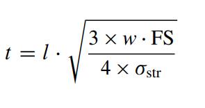 | |||
| Required | 0.424867535 | m | |
| Provided | 0.7 | m | |
| Stone thickness provided is ok to bear the desire pressure |
To simplify in words, on application of lateral load, we have calculated the required thickness that would withstand the load, which comes to 42mm. and in project case we use a stone of 70mm.
Hence we can say safely that the stone has capacity to withstand the calculated load
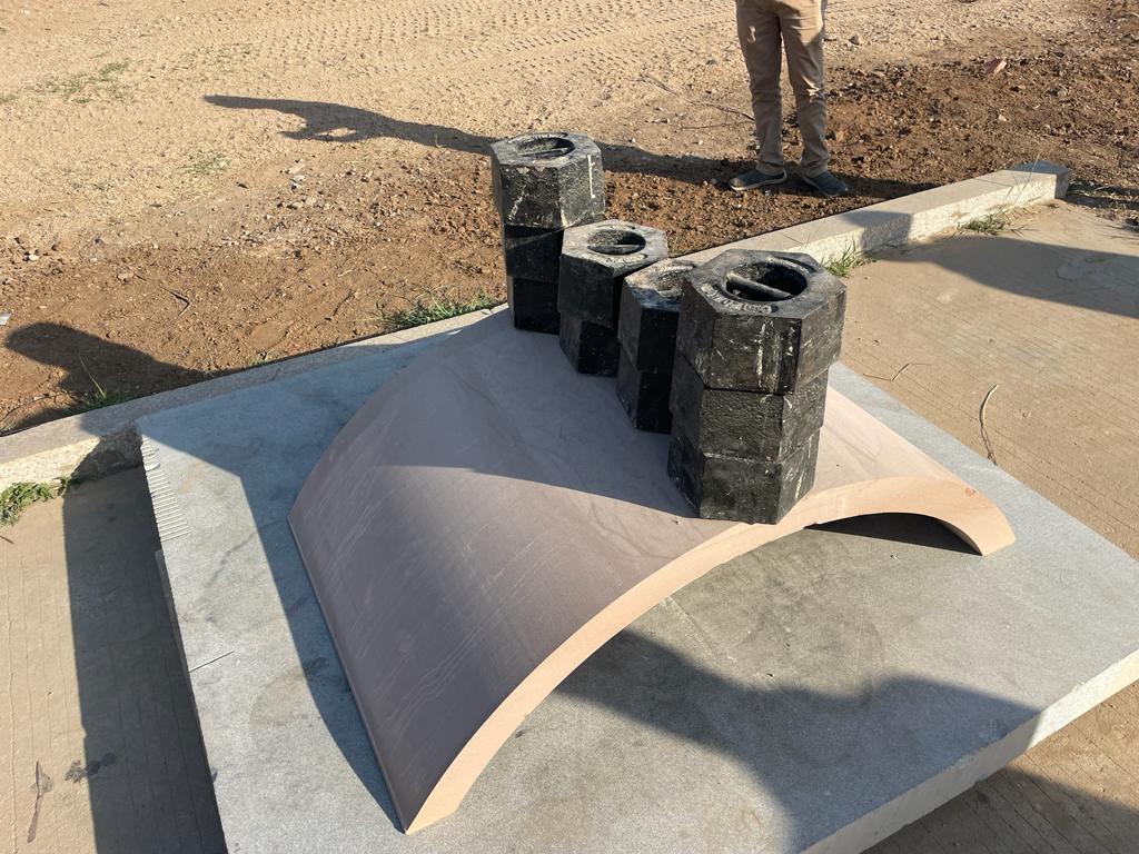
Application of 400Kg Weight of Single Stone Cladding to Check the Practical Strength
Leave a Reply