
CARBON WRAP STRENGTHENING DESIGN TO INCREASE LOAD CAPACITY
OF
COLUMNS HAVING GRADE LESS THAN REQUIREMENT
AT
XXXXXXX, SECTOR 158, NOIDA, UTTAR PRADESH
 |  |
STRUCTURAL CONSULTANTS
O.B DEVELOPERS
(STRUCTURE AUDIT AGENCY)
F-14, Kalkaji Main Road
New Delhi-110019
MOB: +91-9717924616
structureauditagency@gmail.com
Table of Content
| S.No. | Description of NDT Reports |
| 1 | Introduction, Product Data and Assumption, Load Calculations & Carbon Wrap Design |
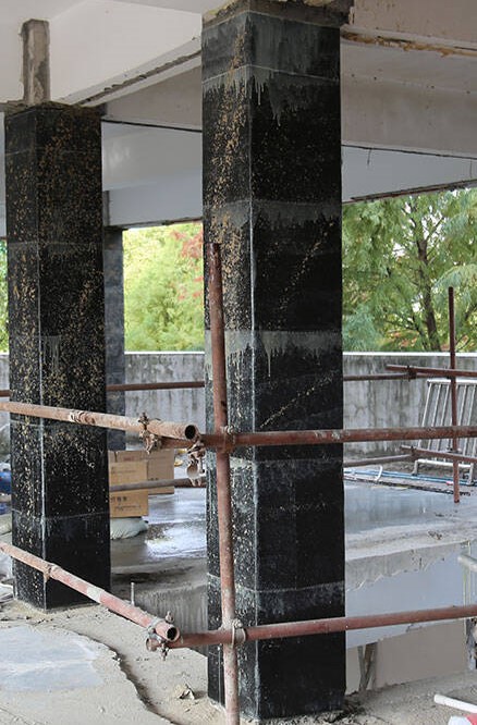
- INTRODUCTION
The structural columns at of XXXXX, SECTOR 158, NOIDA, UTTAR PRADESH. M/s YYYYYYY has requested to M/s OB DEVELOPERS (STRUCTURAL AUDIT AGENCY) for designing the carbon fibre wrap to increase the structure column load carrying capacity which was reduced due to low grade of concrete.
- 1 Code Followed:-
- ACI 440
2. PRODUCT DATA AND ASSUMPTION
TECHNICAL DATA COMPOSITION MasterBrace FIB 600/50 CFS is composed of a dense network of high strength carbon fibers held in a unidirectional alignment with a light thermoplastic glass fiber cross weave yarn
NOTES:
(1) The nominal fabric thickness is based on the total area of fibers (only) in a unit width. From experience, the actual cured thickness of a single ply laminate (fibers plus saturating resins) is 0.040-in to 0.060-in (1.0-mm to 1.5-mm).
(2) The tensile properties given are those to be used for design. These values are derived by testing cured laminates (per ASTM D3039) and dividing the resulting strength and modulus per unit width by the nominal fabric thickness.
(3) The 0° direction denotes the direction along the length of the fabric. (4) The 90° direction denotes the direction along the width of the fabric.
HOW TO APPLY
SURFACE PREPARATION
MasterBrace FIB 600/50 CFS is applied to surfaces treated with MasterBrace P 3500, MasterBrace F2000 and MasterBrace SAT 4500. Consult the data sheets for these materials for additional details.
APPLICATION
MasterBrace FIB 600/50 CFS is only applied as a component of the MasterBrace System. 1.MasterBrace FIB 600/50 CFSmaterial should be cut to the proper dimensions (dimensions will vary based on project requirements) using heavy duty shears or a utility knife. 2. Cut sections of MasterBrace FIB 600/50 CFS can be temporarily stored by carefully rolling fabric into a 12 in [600 mm] (approximate) roll. Do not fold or crease the fabric. Fabric should be kept free of dust, oils, moisture, and other contaminates at all times. 3.Apply the MasterBrace FIB 600/50 CFS fabric directly into uncured MasterBrace SAT 4500applied on the substrate. There is no need to “pre-wet” the MasterBrace FIB 600/50 CFS fabric with uncured MasterBrace SAT 4500 prior to applying the fabric against the substrate. 4.Using a rib roller or squeegee, press the fabric against the substrate until visual signs of uncured MasterBrace SAT 4500 are observed bleeding through the fabric. The rib roller or squeegee should only be run along the direction of the primary fibers in the fabric. 5.Apply a layer of uncured MasterBrace SAT 4500over the top of the MasterBrace FIB 600/50CFS fabric to completely encapsulate the fabric. Consult with the MasterBrace SAT 4500 datasheet on details for applying MasterBrace SAT 4500.
MAINTENANCE
Periodically inspect the applied material and repair localized areas as needed. Consult a Master Builders Solutions representative for additional information. Visit us on the web for the most current product information and news: www.master-builders-solutions.com/ en-us. FOR BEST PERFORMANCE • Use caution when applying MasterBrace FIB 600/50 CFS around sensitive electrical equipment. Carbon fiber filaments can become airborne, infiltrate electrical equipment and cause electrical shorts. • Make certain the most current versions of product data sheet and SDS are being used; call Customer Service (1-800-433-9517) to verify the most current version. • Proper application is the responsibility of the user. Field visits by Master Builders Solutions personnel are for the purpose of making technical recommendations only and are not for supervising or providing quality control on the jobsite.
WARNING
MasterBrace Fiber Reinforcements contain carbon, glass, and/or aramid fibers, MasterBrace FIB 600/50CFS contains carbon and glass fibers. While handling MasterBrace FIB 600/50CFS, wear appropriate work clothing to minimize contact. Product Safety Data Sheets (SDS) are available and should be consulted and on hand whenever handling these products. These products are for professional and industrial use only and are only installed by trained and qualified applicators. Trained applicators must follow installation instructions.
3. LOAD CALCULATIONS & CARBON WRAP DESIGN
| For Column C2 300*975 | ||||||
| Design Load | Load as per Concrete Test | |||||
| Load Capacity of Column | Load Capacity of Column | |||||
| Size of Column | Size of Column | |||||
| D1 | 300 | mm | D1 | 300 | mm | |
| D2 | 975 | mm | D2 | 975 | mm | |
| Ac (D1xD2) | 292500 | sqmm | Ac (D1xD2) | 292500 | sqmm | |
| Grade of Concrete | Grade of Concrete | |||||
| Fck | 40 | N/mm2 | Fck | 20 | N/mm2 | |
| Grade of Steel | Grade of Steel | |||||
| Fy | 500 | N/mm2 | Fy | 500 | N/mm2 | |
| Steel Details | Steel Details | |||||
| Ast | 3720 | sqmm | Ast | 3720 | sqmm | |
| Factor Load It can Carry | Factor Load It can Carry | |||||
| Pu | = | 1.5 x P | Pu | = | 1.5 x P | |
| Pu= 0.4*Fck*Ac + 0.67*Fy*Asc. | Pu= 0.4*Fck*Ac + 0.67*Fy*Asc. | |||||
| Pu | 5926200 | N | Pu | 3586200 | N | |
| Pu1 | 5926.2 | KN | Pu2 | 3586.2 | KN | |
| Pud (Variation in load capacity due to grade of concrete reduction)= Pu1 -Pu2 | ||||||
| Pud | 2340 | KN |
| Carbon Wrap-Column Design Data for C2 | ||||
| Data Required | ||||
| Column Size | B | 300 | mm | |
| D | 975 | mm | ||
| Ast Provided | = | 3720 | sqmm | |
| Ag | B x D | 292500 | sqmm | |
| Fck Provided | = | 23 | N/sqmm | As per NDT |
| Fy | = | 500 | N/sqmm | |
| Fck Required | = | 40 | N/sqmm | |
| Calculation as per ACI 440.2R | ||||
| Step 1 Computation of Design FRP Material Properties | ||||
| To be consider as per material data provided by manufacture- MasterBrace FIB 600/50 CFS | ||||
| Ultimate Tensile Strength | = | 3800 | N/sqmm | |
| Rupture Strain | = | 0.0167 | mm/mm | |
| Step 2 Determining of Existing Axial Compressive Strength | ||||
| Pu2 or | ɸPn | 2390.666667 | KN | Unfactored |
| (As Calculated in Previous Sheet Data) | ||||
| Step 3 Determining of Required Axial Compressive Strength | ||||
| Pu1 or | ɸPn | 3950.666667 | KN | Unfactored |
| (As Calculated in Previous Sheet Data) | ||||
| Step 4 Determining of Required Maximum Compressive Strength of Confined Concrete Fcc | ||||
| Fcc’ | = | 23.37393374 | N/sqmm | |
| ɸ | = | 0.65 | (As per Clause 9.3.2.2 in ACI 318-05) | |
| Step 5 Determining of Required Maximum Confined Pressure Due to the FRP Jacket | ||||
| wf | = | 0.95 | ||
| rc | = | 25 | (Minimum radius at corner) | |
| Pg= | Ast/Ag | 0.012717949 | (Existing Log. Steel ratio) | |
| Where | ||||
| Ae/Ac | = | 0.461649894 | ||
| Ka | = | 0.043706499 | ||
| F1 | = | 2.729047463 | ||
| Step 6 Determining of Number of Layers n | ||||
| Where | ||||
| Ef | 227000 | Mpa | (Modulus of Elasticity of Carbon Fibre) | |
| tf | 0.33 | mm | (Thickness of one carbon fibre layer) | |
| efe= | Ke*efu | 0.009185 | ||
| Where | Ke= | 0.55 | (FRP Strain Efficieny Factor) | |
| D= | 976.98 | mm | ||
| Therefore | ||||
| n | = | 2.026815711 | Nos | |
| Say | = | 3 | Nos | |
| 6 | ||||
| f1/fc, | 0.1186542 | > | 0.08 | |
| Step 7 Verification of Ultimate Axial Strain of Confined Concrete more than or equal to 0.01 | ||||
| Where | ||||
| Ec’ | 0.0010204 | As per ACI 318-05 | ||
| Shape Factor Kb | 1.7873257 | As per Eq 12-10 in ACI 440.2R | ||
| ECCU= | 0.0085109 | < | 0.01 | |
| Hence Safe | ||||
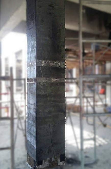
| Provide | 3 | Layers of Carbon Wrapping Sheet on Periphery with Anchor Fastner & 10/1.4 Grove Laminate @ 300mm c/c | ||
| 0.33 | mm Thickness |
Leave a Reply