
PULL OUT/CAPO TEST
FOR
DETERMINING THE IN-SITU
GRADE OF CONCRETE
PROJECT NAME : ANALYSIS THE LOAD CAPACITY OF THE STRUCTURE AND TO RETROFIT IT AS PER LATEST CODE FOR NEXT 10 YEARS LIFE.
PROJECT LOCATION : IOCL, HALDIA, WEST BENGAL
STRUCTURAL CONSULTANTS
O.B DEVELOPERS
(STRUCTURE AUDIT AGENCY)
F-14, Kalkaji Main Road
New Delhi-110019
MOB: +91-9717924616
structureauditagency@gmail.com
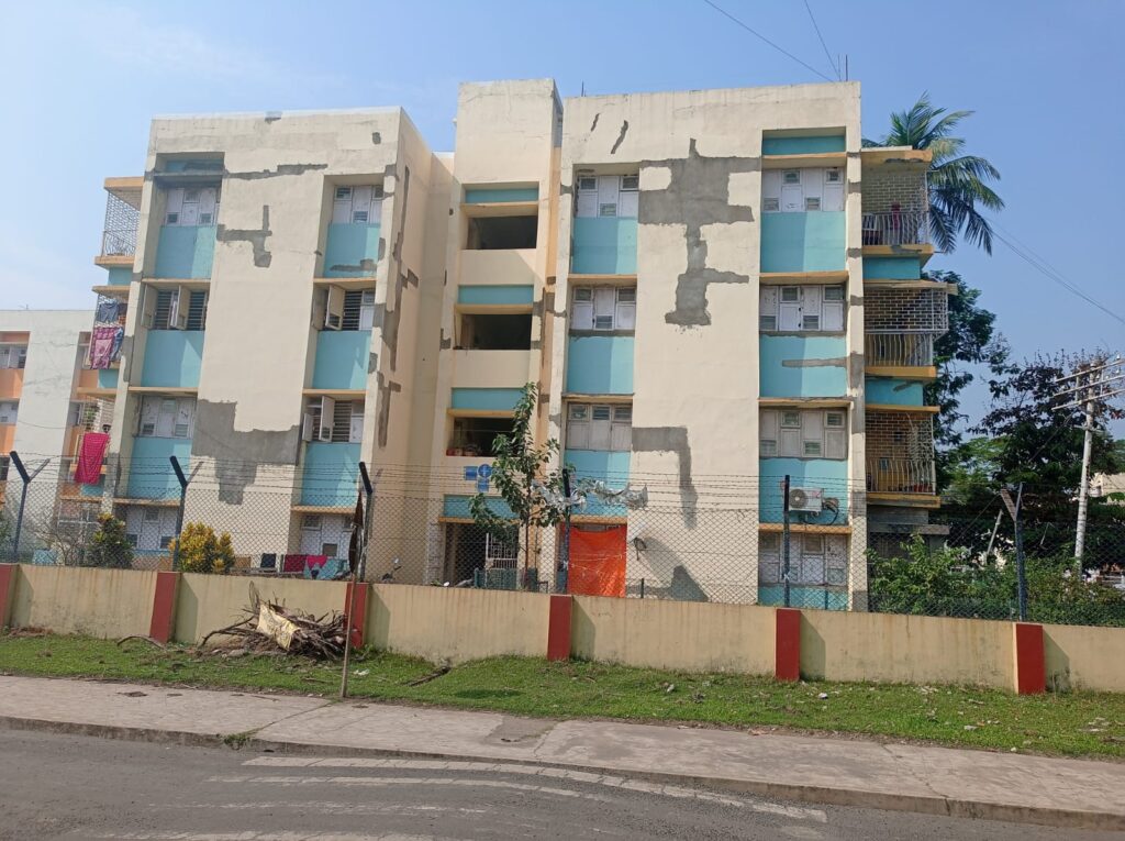
- INTRODUCTION
The structure is a located at Haldia, West Bengal. After going through various method of repair from local consultant the organisation decided to hire a professional audit firm for analysis and retrofitting. M/s O.B Developers (Structure Audit Agency) was requested to check the maximum load carrying capacity of the floor and to make the building fit for next 10 years by retrofitting as per latest code.
.
1.2 Process of Plate Load Testing
1.2.1 Test location:- Location is selected , usually in the middle of the reinforcement mess (50 mm from reinforcement) and is to be minimum 100mm from any edge and corners . If more than one test is required in the same area, test is placed in the same horizontal layer with an internal distance of minimum 200mm, maximum 300 mm.
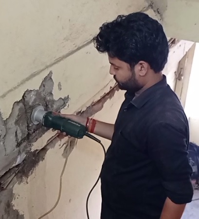
1.2.2 Coring the centre hole, planning the surface and routing the recess:- using a water cooled diamond bit, an 18mm diameter by 60mm deep hole is drilled perpendicular to plane concrete surface. A recess (slot) is routed in the hole to a diameter of 25 mm and at a depth of 25 mm with a diamond tool. A split ring is expanded in the recess and pulled out using a pull machine reacting against a 55 mm diameter counter pressure ring. The concrete in the strut between the expanded ring and the counter pressure ring is in compression.

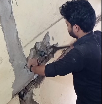
1.2.3 Expansion of capo- insert:- Hold the pull bolt of the expansion unit in the same position with the 12” wrench and turn the big nut clockwise with the 46mm wrench, about 9 rotation. When the expansion of the Capo-Insert has been completed, the thread of the base pull bolt will emerge and a hard resistance will be felt. Then, back off the nut 1/8 rotation anti-clockwise. Still with the base pull bolt kept in the same position with the adjustable wrench.
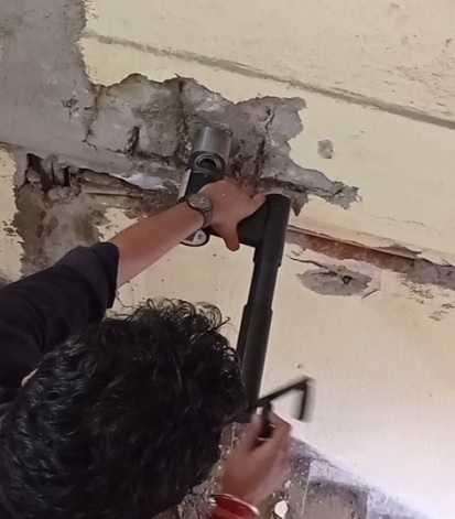
1.2.4 Attachment of the counter pressure and the coupling:-The counter pressure is place around the expansion unit with its plane face resting against the concrete surface. Then thread the coupling on the base pull bolt 2-3 rotations.
1.2.5 Coupling of the hydraulic pull machine:-Make sure the recess of the counter pressure catches the 55 mm in diameter instrument front hole and make it ready to be loaded
1.2.6 Pull out:- Hold one hand on the pistol handle between the two cylinders of the pull machine. Loading is commenced by turning the loading handle (use the outer handle knob) clock-wise at a speed of about one rotation per two seconds, constantly all the time, until rupture occurs. The digital display will indicate the pull force in kN (kilo Newton). Before the peak-load occurs, the kN-loading rate will decrease. Keep on turning the handle with one rotation every two seconds. After the peak-load has been reached, the handle is turned quickly clock-wise until no more travel is left on the telescope handle.
1.2.7 Transforming the pullout load to compressive strength–
Then pull out force (Fu) is measured in kN and transformed to compressive strength (Fck) in MPa (or Psi) with the help of calibration chart.
Reference
• ASTM C-900-87
• BS 1881
• DS 423.
• AS3850
Leave a Reply