
Prepared By:-
O.B DEVELOPERS
(STRUCTURE AUDIT AGENCY)
F 14, Kalkaji Main Road , New Delhi-110019
Email- strutureauditagency@gmail.com
Call-+91-9717924616
www.structureauditagency.com
Executive Summary:
Based on the Visual Inspection & NDT Results
Of all the Structural Members of the Existing Building
- In order to assess the structural stability of the building, following tests were conducted at site
- Rebound Hammer Test as per IS: 13311 (Part-2)-1992 for determining the estimated compressive strength and uniformity of concrete in terms of surface hardness test
- Ultrasonic Testing (UT) to determine the existing thickness of steel structure. It uses high frequency sound energy to conduct examinations and make measurements. Ultrasonic inspection can be used for flaw detection/evaluation, dimensional measurements, material characterization, and more
- Hardness Testing to determine the yield strength of the steel structure.
- Section Verification: A detailed investigation is required to fulfill the requirements of section verification in which detailed all structural steel members.
- Ultrasonic Pulse Velocity Test as per IS: 516 (Part-5/Sec1)-2018 for ascertaining the quality of concrete, soundness and density of concrete.
- As Built Drawing preparation as per site measurements.
- Based on site investigation, test reports and the observations regarding structural deterioration of building following conclusion are drawn below :
- There is no durability problem related with strength of concrete materials.
- Present steel percentage in RCC sections is taken as steel percentage in structural stability analysis of building because there is no possibility of de-rating of steel tensile strength due to weathering effect.
- The structural adequacy of RCC sections is possible because existing concrete grade is more than minimum required concrete grade. Detailed analysis report of structural stability is attached as an annexure.
3. Structure Analysis: As per the test results and analysis the main reason for the slab deflection is insufficient depth of the steel member as per the span of the member. As per IS 800/ IS 456 the span to depth ratio is not fulfilling the criteria hence causes more the allowable deflection on site during live and dead load.
Table of Contents
| Sr.No. | Description of NDT Reports | |
| 1 | Introduction, Scope of Work | |
| 2 | NDT Test Results & Interpretation | |
| 3 | Analysis & Recommendations | |
1. Introduction
- Introduction
- The existing structure at xxx, Okhla, New Delhi Having Basement+ G+3 storied R.C.C+Steel framed structure. M/s ABCD Packers Limited has awarded the work to O.B Developers for conducting condition assessment of RCC structures using Non-destructive testing.
This report pertains to the asserted safety appraisal and structural health assessments standards. In this report description of the damaged portions of the building, objectives of the investigation and survey, general methodology and test procedures etc. are given, followed by details of the observations recorded at the site and results of in-situ and laboratory tests.
1.2. Walkover survey and visual inspection
First and foremost activity in a condition survey and structural investigation, especially in distressed building, is a walk over survey or systematic visual inspection so as to gather readily available information about the structure in question.
The visual observations and documentation was made for the RCC structures to determine if there are any obvious signs of distress, deflection or deterioration in the structure. Based on the visual inspection, redistribution of the number of tests to be performed as per the scope of work and their point of conductance were proposed so as to confirm the recommendations and findings of visual inspection.
1.3. Objectives of the overall investigation
The overall objective of the investigation carried out for the structure is to obtain an up to date account of the health condition of the structure so that appropriate repair measures can be taken up to make up for the damages sustained. Keeping this in view the basic objectives of the investigation formulated is as given below.
- To assess the existing condition of the structural elements.
- To determine the extent of damages in the structure, so as to undertake suitable remedial measures for rehabilitation of the structure.
1.4 Scope of work and selection of tests
In-situ tests and laboratory tests have been selected based on the visual inspections carried out and as detailed in the scope of work. The selection of tests has been done so as to meet the overall objective of the NDT study and the observations made during a quick walk over survey. Various Tests were conducted for the evaluation of the Structure:
The various Non-Destructive Tests carried out for health assessment and structural audit of the RCC structures are given below
.
- R Rebound Hammer Test: For determining the estimated compressive strength of concrete and uniformity of concrete in terms of surface hardness as per IS 13311 (Part-2)-1992.
- Ultrasonic Pulse Velocity Test as per IS: 516 (Part-5/Sec 1)-2018 for ascertaining the quality of concrete, soundness and density of concrete.
- Section Verification: To check dimensional conformance & section verification of structure.
- Thickness Testing to check reduction of thickness in steel members because of corrosion.
- NDT is a way of testing which includes number of methods to evaluate component/structure/material behavior without destroying the structure.
- Slab Deflection Analysis as per indian standards and codes.
- Retrofitting of Slab Deflection to bring the deflection within control limit as per indian standards and codes.
2. NDT TEST RESULTS & INTERPRETATION
Test Certificate:- Rebound Hammer TEST
| Quality Assurance in Concrete using Non Destructive Testing | |||||||||||
| Client:- M/s ABCDE Packers Limited | Consultant :- OB Developers | ||||||||||
| Non Destructive Testing at XXXX, Okhla, New Delhi | |||||||||||
| S. No./Location | Rebound Hammer Test | ||||||||||
| SL. No. | Sample Identification/ Location | Hammer Alignment | Rebound No. | Avg. Rebound No. | Quality Of Concrete | Estimated Concrete Strength N/mm2 | |||||
| BASEMENT | |||||||||||
| 1 | Slab | Vertical up | 44 | 46 | 42 | 50 | 52 | 46 | 47 | Very Good Layer | 28.44 |
| 2 | Slab | Vertical up | 44 | 44 | 42 | 44 | 46 | 50 | 45 | Very Good Layer | 27.21 |
| GROUND FLOOR | |||||||||||
| 3 | Slab | Vertical up | 34 | 32 | 36 | 38 | 36 | 32 | 39 | Good Layer | 26.78 |
| 4 | Slab | Vertical up | 38 | 36 | 34 | 36 | 34 | 40 | 36 | Good Layer | 20.81 |
| 5 | Slab | Vertical up | 44 | 40 | 38 | 38 | 40 | 42 | 40 | Very Good Layer | 23.76 |
| 6 | Slab | Vertical up | 32 | 38 | 30 | 34 | 36 | 32 | 39 | Good Layer | 26.78 |
| FIRST FLOOR | |||||||||||
| 7 | Slab | Vertical up | 36 | 30 | 32 | 34 | 38 | 36 | 34 | Good Layer | 23.33 |
| 8 | Slab | Vertical up | 36 | 42 | 38 | 30 | 32 | 32 | 35 | Good Layer | 23.83 |
| 9 | Slab | Vertical up | 30 | 32 | 28 | 32 | 32 | 34 | 31 | Good Layer | 21.12 |
| 10 | Slab | Vertical up | 38 | 38 | 34 | 34 | 36 | 34 | 36 | Good Layer | 24.32 |
| Rebound Hammer(ASTM C 805- 85):- Surface Hardness indices value should be more than | |||||||||||
| 28 to get correlation with estimated strength , uniformity of concrete |
INTERPRETATION OF RCC SURFACE CONDITION, UNIFORMITY OF CONCRETE AND FCK VALUE OF CONCRETE OBTAINED FROM REBOUND HAMMER:-
A .Test results analysis of the Rebound Number values is based on test results conducted over concrete surfaces. Obtained test results explain about pattern of concrete quality of whole structure sections in terms of surface hardness. Statistical data shows that dominating percentage of quality of concrete is in range of M23. Concrete surfaces are not suffering from surface hardness problem.
Test Certificate:- ULTRASONIC PULSE VELOCITY TEST
| Quality Assurance in Concrete using Non-Destructive Testing | |||||||
| Client: – M/s ABCDE Packers Limited | Consultant :- OB Developers | ||||||
| Non Destructive Testing at XXXX, Okhla, New Delhi | |||||||
| S. No./Location | Ultrasonic Pulse Velocity | ||||||
| SL. No. | Sample Identification/ Location | Type of surface | Distance (mm) | Travel Time (micro sec.) | Av. Velocity (km/sec) | Direct Proportionate Velocity (IS, 5.4.1 13311 part 1) | Concrete Quality |
| BASEMENT | |||||||
| 1 | Slab | Indirect | 300 | 59.10 | 5.08 | 6.08 | Excellent |
| 2 | Slab | Indirect | 300 | 61.80 | 4.85 | 5.85 | Excellent |
| GROUND FLOOR | |||||||
| 3 | Slab | Indirect | 300 | 61.30 | 4.89 | 5.89 | Excellent |
| 4 | Slab | Indirect | 300 | 62.43 | 4.81 | 5.81 | Excellent |
| 5 | Slab | Indirect | 300 | 73.21 | 4.10 | 5.10 | Excellent |
| 6 | Slab | Indirect | 300 | 96.81 | 3.10 | 4.10 | Good |
| FIRST FLOOR | |||||||
| 7 | Slab | Indirect | 300 | 59.80 | 5.02 | 6.02 | Excellent |
| 8 | Slab | Indirect | 300 | 63.40 | 4.73 | 5.73 | Excellent |
| 9 | Slab | Indirect | 300 | 81.39 | 3.69 | 4.69 | Excellent |
| 10 | Slab | Indirect | 300 | 61.00 | 4.92 | 5.92 | Excellent |
| 11 | Slab | Indirect | 300 | 51.60 | 5.81 | 6.81 | Excellent |
| USPV (IS:13311 part 1):- Concrete Quality Grading(km/sec) Above 4.5 – Excellent, 3.5 – 4.5 – Good , 3.0 – 3.5- Medium & Below 3.0- Doubtful |
Analysis of uniformity and imperviousness of concrete on the basis of USPV test results: –
USPV makes possible an examination of material homogeneity. Analyzing the ultrasonic velocity wave propagation variations, it is possible to verify the compact of the structure or detect heterogeneous regions. The ultrasonic test methodology in concrete is based on the fact that the propagation time expresses the density of the material. Histogram of USPV test results is analyzed in same pattern as rebound hammer is done but basic difference is that USPV results are interrelated in terms of density and rebound hammer results are interrelated in terms of surface hardness. It has non-uniform concrete quality in terms of density. There are indications of air-pockets and voids as significant from USPV test results as per IS: 516 Part 5/Sec 1:2018. Statistical data says that over all concrete has uniform (Good-Excellent) grade of quality of density pattern.
TEST CERTIFICATE THICKNESS MEASUREMENT
| Thickness of Steel Members | ||||
| Non Destructive Testing at XXXX, Okhla, New Delhi | ||||
| SI No | Location | Thickness Reading | ||
| Web | Flange-1 | Flange-2 | ||
| 1 | Beam | 7.5 | 11.4 | 10.6 |
| 2 | Beam | 5 | corrode | corrode |
| 3 | Beam | corrode | corrode | corrode |
| 4 | Beam | 7.5 | 10.7 | 11.3 |
| 5 | Beam | 7.5 | 11.4 | 11.8 |
| 6 | Beam | 6.7 | 10.3 | 11.5 |
| 8 | Beam | 7.2 | 12.2 | 12 |
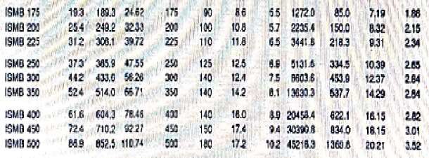
As per Indian Steel Table
Hardness Testing
The determination of the hardness of metallic materials according to Leeb is defined in the ISO 16859 and ASTM A956 standards. In this dynamic test method, the ratio of rebound velocity to impact velocity of a moving impact body is used to determine the hardness. Conversion of leeb value to vickers hardness value to evaluate the tensile strength of steel members as per IS 4258-1992.
Hardness Testing Certificate
| Hardness of Steel Members | ||||||||||
| Non Destructive Testing at XXXX, Okhla, New Delhi | ||||||||||
| Sl. No. | Location | Vicker Hardness | Tensile Strength | Yield strength | ||||||
| Flange-1 | WEB | Flange-2 | Flange-1 | WEB | Flange- 2 | Flange- 1 | WEB | Flange-2 | ||
| 1 | Beam | 161 | 111 | 130 | 514 | 354 | 415 | 308 | 212 | 249 |
| 2 | Beam | 96 | 98 | — | 308 | 314 | — | 185 | 188 | — |
| 3 | Beam | 139 | — | — | 446 | — | — | 268 | — | — |
| 4 | Beam | 117 | 131 | 145 | 376 | 418 | 465 | 226 | 251 | 279 |
| 5 | Beam | 113 | 136 | 213 | 362 | 434 | 684 | 217 | 260 | 410 |
| 6 | Beam | 130 | 111 | 186 | 415 | 354 | 598 | 249 | 212 | 359 |
| 7 | Beam | 113 | — | 101 | 362 | — | 323 | 217 | — | 194 |
| 8 | Beam | 159 | 100 | 110 | 507 | 320 | 350 | 304 | 192 | 210 |
| 9 | Beam | 106 | — | — | 338 | — | — | 203 | — | — |
| 10 | Beam | 165 | 162 | 165 | 530 | 518 | 530 | 318 | 311 | 318 |
Floor Vibration Analysis
Analysis & Recommendations
- VARIOUS CODE REFERED DURING ANALYSIS AND DESIGN
- IS 800
- IS: 1893
- IS 875
- Method of structural adequacy analysis and design parameters
The seismic safety of a multistoried reinforced steel building will depend upon the initial architectural and structural configuration of the entire building. The methodology of the Structural analysis, design and detailing of the structural frame work will be resorted to achieve stability in each aspect and its ductile performance under severe seismic lading. Due consideration should be given to the aspect of fabrication and connection. Any weakness, if left in the structure, either in the design or in the fabrication will be fully reflected during the postulated design seismic loading for the seismic zone in the earthquake code IS: 1893 Part IV.
- Assumptions in static analysis
The basic assumptions in static analysis methodology are as follows: –
- The behavior of the structure is assumed to be perfectly linear and deformations are small
- All joints are rigid
- The members are subjected to axial, flexural and shear deformations
- The force deformation relationship remains linear during the entire load regime.
- Most critical section of building is selected for analysis where building section has soft storey
- Mathematical Modelling
The structure is idealized as a 3-D space frame model. The beams and columns are modelled as flexural members. The columns are idealized to be pinned at the foundation level.
- Loads for Superstructure and Sub structural elements:
| a) | Steel | : Fe250 |
| b) | Density of Steel | : 78kN/m³ |
| c) | Self-weight factor | : 1.5(Including Weight of paint, rusting etc.) |
| d) | Dead load | : 4.75kN/sqm |
| e) | Live Load | : 5KN/sqm |
- Materials properties data for static analysis
- Steel Sections
Conforming to IS 808 -1989
Yield strength Fy : 250 N/mm2 Static modulus of elasticity Es : 2 x 10⁵ N/mm2
- Load Factors for Plastic Design of Steel Structures
Combination of Loads considered in analysis: The structural design has been carried out in accordance with the provisions of the codes IS: 1893(Part-I) for Normal design conditions
In the plastic design of steel structures, the following load combinations shall be accounted for:
- 1.7 (DL + SIDL + IL),
- 1.7 (DL + SIDL) + EL, and
- 1.3 (DL + SIDL + IL + EL)
RETROFITTING METHODOLOGY
| S.NO | PARTICULAR | Methodology |
| 1 | 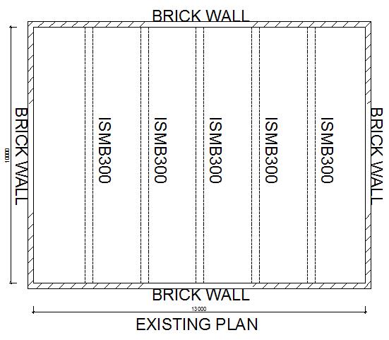 | As built plan prepared as per site physical measurement Before retrofitting vibration is 17.5mm |
| 2 | 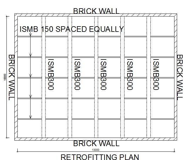 | There is a need to introduce 5 nos ISMC 150 equally spaced throughout length of beam just to divide the beam into small parts After retrofitting vibration is 3.5mm |
| 3 | 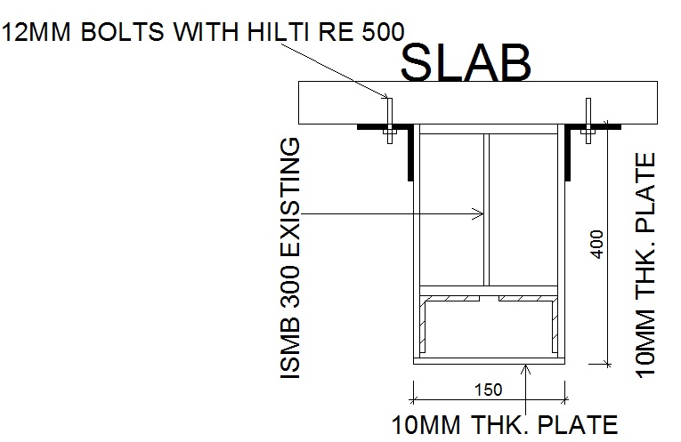 | 1. PLACE 10MM THICK PLATE ON BOTH SIDE OF THE EXISTING ISMB 300. 2. BOTTOM PLACE ISA 75X75X6 AND WELD IT WITH EXISTING ISMB AND NEW 10MM PLATE. 3.PLACE ISA 75X75X6 AT TOP OF BOTH SIDE AND REBAR WITH 12MM BOLTS @ 400MM C/C UPTO 90MM DEPTH. |
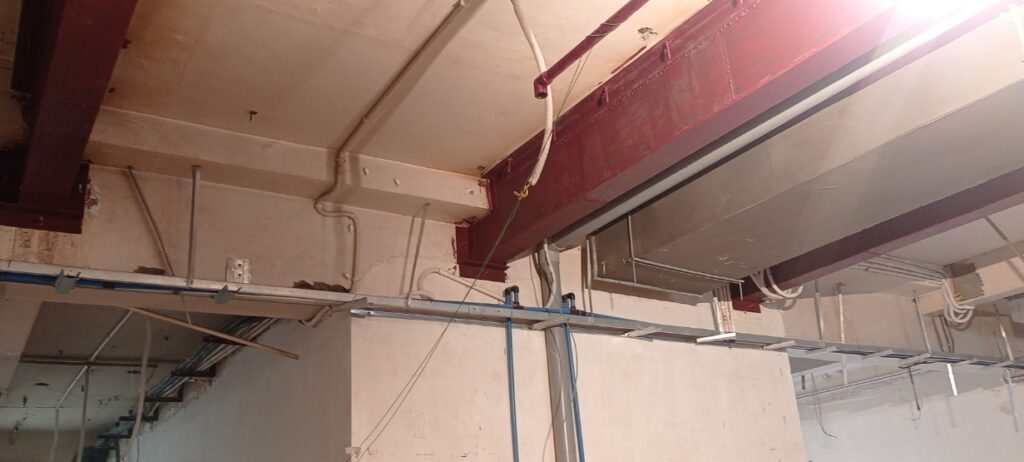
 Photo Before Retrofitting Photo Before Retrofitting |
 Photo After Retrofitting Photo After Retrofitting |
Leave a Reply