
Executive Summary:
Based on the Visual Inspection & NDT Results
Of all the Structural Members of the Existing Building
- In order to assess the structural stability of the building, following tests were conducted at site
- Rebound Hammer Test as per IS: 13311 (Part-2)-1992 for determining the estimated compressive strength and uniformity of concrete in terms of surface hardness test
- Cover Meter Test as per IS 456:2000 to measure the clear cover of structure members.
- Structural section detailing: Preparation of structural drawings by using proof-meter, Profometer for measuring the cover depth and existing protecting layer of steel rebar, and number of rebars for beam column frame system only. Profometer test to ascertain the location & spacing of the rebars and cover of concrete provided to the rebars as per code BS1881; 204. We have done independent cross check of steel rebars and section details of RCC sections. In addition to above, the concrete covers of the RCC members were removed to expose the rebars to physically verify. Our results obtained from proof-meter test are tallying with the results available at exposed RCC sections.
- Estimated strength is based rebound hammer values. Statistical data shows that dominating percentage of quality of concrete is in the range of M19 for all types of RCC sections. Concrete surfaces are not suffering from surface hardness problem and there are no indications of blistering of concrete surface as per IS 13311 (Part-2)-1992. Structure has variable pattern of concrete quality in terms of surface hardness
- Based on site investigation, test reports and the observations regarding structural deterioration of building following conclusion are drawn below :
- There is no durability problem related with strength of concrete materials.
- Present steel percentage in RCC sections is taken as steel percentage in structural stability analysis of building because there is no possibility of de-rating of steel tensile strength due to weathering effect.
- The structural adequacy of RCC sections is possible because existing concrete grade is more than minimum required concrete grade. Detailed analysis report of structural stability is attached as an annexure.
- Summary for structural adequacy analysis
- The structure is unsafe for loading as per IS 456:2000 and SP 16 for service load of dead and live load.
Table of Contents
| Sr. No. | Description of NDT Reports | Page No. | ||
| 1 | Introduction, Scope of Work | 4-5 | ||
| 2 | Testing Procedure for NDT | 6-8 | ||
| 3 | NDT Test Results & Interpretation | 9 | ||
| 3.1 | General Introduction | 10 | ||
| 3.2 | Rebound Hammer Test Results & Interpretation | 11-12 | ||
| 3.3 | Cover Test Results & Interpretation | 13 | ||
| 4 | Annexure 1 – Relevant Testing Code -Structure Adequacy Analysis | |||
1. Introduction
- Introduction
The existing structure at Barasat indira gandhi memorial high school 18 Jessore Rd, Barowaritola, Barasat, Kolkata, West Bengal pin-700124 is G+4 storied RCC framed structure condition assessment of RCC structures using Non-destructive testing.
This report pertains to the asserted safety appraisal and structural health assessments standards. In this report description of the damaged portions of the building, objectives of the investigation and survey, general methodology and test procedures etc. are given, followed by details of the observations recorded at the site and results of in-situ and laboratory tests.
1.2. Objectives of the overall investigation
The overall objective of the investigation carried out for the structure is to obtain an up to date account of the health condition of the structure so that appropriate repair measures can be taken up to make up for the damages sustained. Keeping this in view the basic objectives of the investigation formulated is as given below.
- To assess the existing condition of the structural elements.
- To determine the extent of damages in the structure, so as to undertake suitable remedial measures for rehabilitation of the structure.
1.3 Scope of work and selection of tests
In-situ tests and laboratory tests have been selected based on the visual inspections carried out and as detailed in the scope of work. The selection of tests has been done so as to meet the overall objective of the NDT study and the observations made during a quick walk over survey. Various Tests were conducted for the evaluation of the Structure:
The various Non-Destructive Tests carried out for health assessment and structural audit of the RCC structures are given below
- Rebound Hammer Test: For determining the estimated compressive strength of concrete and uniformity of concrete in terms of surface hardness as per IS 13311 (Part-2)-1992.
- Cover Meter Test: Conducting cover meter test at selected locations on RCC members of the structures covered under the study to see the adequacy of concrete cover to rebars and effect of carbonation.
- Structure Analysis: To Analysis the maximum load that roof slab can carry safely as per IS 456:2000 and SP 16 in Seismic Zone 4.
2. TESTING PROCEDURE
2.1 Rebound Hammer Test:-
Purpose:-
This test gives a measure of the surface hardness of the concrete surface. Although there is no direct relationship between this measurement of surface hardness and strength, an empirical relationship exists.
Objective of testing:-
Rebound hammer test is performed to determine the following:
- Surface hardness
- Uniformity of concrete
- Quality of concrete in respect to standard requirements and comparative analysis
- Estimated strength which is derived from establishing a relationship between in-situ core strength and rebound index.
References:-
- BS 6089:1981 and BS 1881:Part 202,
- IS13311(Part2):1992
- ASTM C 805-02
- BS EN13791:2007
Influencing factors:-
Rebound hammer test results are considerably influenced by these factors:
- Size, shape and rigidity of the specimen
- Age of test specimen
- Smoothness of surface and internal moisture condition of the concrete
- Carbonation of concrete surface
Testing Method:-
According to ASTM C 805-02 clause 7.1 the concrete members to be tested shall be at least 100mm thick and fixed within a structure. Trowelled surfaces generally exhibit high rebound numbers than screed or formed finishes. Do not compare the test results if the form material against which the concrete is placed is not similar. Heavily textured, soft or surfaces with loose mortar shall be ground flat with abrasive stone. Smooth formed or trowelled surfaces do not have to be ground prior to testing. Also this test is not conducted directly over the reinforcing bars having cover less than 20mm. The surface under test should be clean and smooth because rough surfaces cannot be tested as they do not give reliable results. Dirt or other loose material on the surface can be removed using a grinding stone prior to test.
2.2 CONTOUR MAPPING OF COVER DEPTH IN RCC STRUCTURE BY USING PROFOMETER: AN IN-SITU TEST
Purpose
The Profometer has been used for the non-destructive location of steel bar and for the measurement of concrete cover, using the eddy current principle with pulse induction as the measuring method. This machine works on magnetic field generation and by creating a full current circle with help of hidden steel bar machine maps the cover depth and diameter of steel bar.
Application
- Quality control, to ensure correct location and cover to reinforcing bars after concrete placement or in existing RCC structures,
- Investigation of concrete members and locating reinforcement as a preliminary to some form of testing, such as, core extraction or UPV.
Objective of testing
Test is performed to determine the following:
- Cover depth
- Relation between Protective Layer/cover depth V/S penetration depth of deleterious agent
References
- BS 1881 Part 204
- B5707-2003
3. TEST RESULTs INTERPRETATION
3.1 General Introduction
3.2 REBOUND HAMMER Test:-
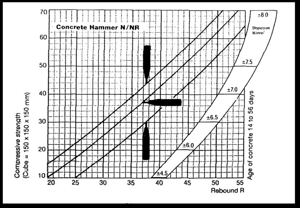
Test results analysis of the Rebound Number values is based on test results conducted over concrete surfaces. Obtained test results explain about pattern of concrete quality of whole structure sections in terms of surface hardness. So there is no indication of blistering of concrete surface as per IS 13311 (Part-2)-1992. Estimated strength of concrete calculated from rebound hammer number is based on correlation graph between core strength v/s corresponding rebound hammer values. Rebound hammer has been carried out in all three directions horizontal, vertical down and vertical up. By using manufacturer graph, all vertical up/vertical down rebound hammer readings has been converted into the equivalent horizontal readings.Histogram plot of the Rebound Number values is based on test results conducted over concrete surfaces. Histogram plot explains about pattern of concrete quality of whole structure sections in terms of surface hardness. Rebound number helps to obtained Estimation of Strength of concrete from correlation between Rebound Hammer V/S Core Compressive strength. Estimated strength of concrete (obtained from correlation between Rebound Hammer V/S Core Compressive strength in table & fig ) is explained in the table
Figure
Reference for Test Certificate of Rebound hammer & Ultrasonic Pulse Velocity Test table
| For Rebound hammer Test | ||
| 1 | Sample Identification/Location | Location where test are conducted |
| 2 | Hammer Alignment | Direction of hammer |
| 3 | Rebound No. | Horizontal proportionate of rebound nos. from manufacturer calibration graph |
| 4 | Avg. Rebound No. | Rebound hammer no. obtained from instrument |
| 5 | Estimated Strength (MPa) | Correlation equation between RH and Core Value(ref equation figure 3.2) |
TEST CERTIFICATE:- REBOUND HAMMER TEST
| Quality Assurance in Concrete using Non Destructive Testing | ||||||||||||||||||||||
| Client:- DESIGN CENTER | Consultant :-OB Developers | |||||||||||||||||||||
| Non Destructive Testing of Barasat Indira Gandhi Memorial High School | ||||||||||||||||||||||
| S. No./Location | Rebound Hammer Test | |||||||||||||||||||||
| S.No | Sample Identification/ Location | Hammer Alignment | Rebound No. | Avg. Rebound No. | Quality Of Concrete | Estimated Strength (MPa) | ||||||||||||||||
| GROUND FLOOR | ||||||||||||||||||||||
| 1 | Director room corridor | Column | Horizontal | 28 | 26 | 24 | 24 | 22 | 26 | 25 | Fair | 17.5 | ||||||||||
| 2 | Room No. 3 corridor | Column | Horizontal | 40 | 36 | 42 | 38 | 40 | 38 | 39 | Good Layer | 27.3 | ||||||||||
| 3 | Room No. 2 | Column | Horizontal | 36 | 34 | 36 | 34 | 38 | 40 | 36 | Good Layer | 25.4 | ||||||||||
| 4 | Room No. 3 | Column | Horizontal | 38 | 34 | 38 | 32 | 34 | 36 | 35 | Good Layer | 24.7 | ||||||||||
| 5 | Staff Room front | Column | Horizontal | 22 | 26 | 24 | 30 | 26 | 40 | 28 | Fair | 19.6 | ||||||||||
| 6 | Room No. 9 | Column | Horizontal | 28 | 26 | 26 | 30 | 28 | 30 | 28 | Fair | 19.6 | ||||||||||
| 7 | Room No. 9 | Column | Horizontal | 34 | 38 | 34 | 32 | 42 | 40 | 37 | Good Layer | 25.6 | ||||||||||
| FIRST FLOOR | ||||||||||||||||||||||
| 1 | Room No. 10 front | Column | Horizontal | 32 | 34 | 28 | 30 | 28 | 30 | 30 | Good Layer | 21.2 | ||||||||||
| 2 | Room No. 11 | Column | Horizontal | 34 | 36 | 32 | 30 | 28 | 30 | 32 | Good Layer | 22.1 | ||||||||||
| 3 | Room No. 12 | Column | Horizontal | 32 | 34 | 30 | 32 | 32 | 34 | 32 | Good Layer | 22.6 | ||||||||||
| 4 | Room No. 16 front | Column | Horizontal | 36 | 28 | 36 | 32 | 34 | 34 | 33 | Good Layer | 23.3 | ||||||||||
| 5 | Room No. 16 | Column | Horizontal | 38 | 40 | 34 | 36 | 34 | 36 | 36 | Good Layer | 25.4 | ||||||||||
| 6 | Room No. 17 | Column | Horizontal | 40 | 36 | 34 | 42 | 34 | 38 | 37 | Good Layer | 26.1 | ||||||||||
| Rebound Hammer(ASTM C 805- 85):- Surface Hardness indices value should be more than 28 to get correlation with estimated strength , uniformity of concrete | ||||||||||||||||||||||
INTERPRETATION OF RCC SURFACE CONDITION, UNIFORMITY OF CONCRETE AND FCK VALUE OF CONCRETE OBTAINED FROM REBOUND HAMMER:-
A .Test results analysis of the Rebound Number values is based on test results conducted over concrete surfaces. Obtained test results explain about pattern of concrete quality of whole structure sections in terms of surface hardness. Statistical data shows that dominating percentage of quality of concrete is in range of M19. Concrete surfaces are not suffering from surface hardness problem. There is also no indication of blistering of concrete surface as per IS 13311 (Part-2)-1992. Estimated strength is based rebound hammer values. Statistical data shows that dominating percentage of quality of concrete is in the range of M23 for all types of RCC sections.
Test Certificate:- cOVER METER
| Quality Assurance in Concrete using Non Destructive Testing | |||
| CLIENT; | CONSULTANT: O.B.DEVELOPERS | ||
| Non- dective testing of | |||
| S. No./Location | Rebound Hammer Test | ||
| S.No | Sample Identification/ Location | RCC Cover | Reading No. |
| GROUND FLOOR | |||
| 1 | Director Room Corridor | 42 | Sufficient cover depth as per IS456 2000 |
| 2 | Room No. 3 Corridor | 43 | Sufficient cover depth as per IS456 2000 |
| 3 | Room No. 2 | 44 | Sufficient cover depth as per IS456 2000 |
| 4 | Room No. 3 | 41 | Sufficient cover depth as per IS456 2000 |
| 5 | Staff Room Front | 42 | Sufficient cover depth as per IS456 2000 |
| 6 | Room No. 9 | 42 | Sufficient cover depth as per IS456 2000 |
| 7 | Room No. 9 | 41 | Sufficient cover depth as per IS456 2000 |
| FIRST FLOOR | |||
| 1 | Room No. 10 Front | 44 | Sufficient cover depth as per IS456 2000 |
| 2 | Room No. 11 | 43 | Sufficient cover depth as per IS456 2000 |
| 3 | Room No. 12 | 44 | Sufficient cover depth as per IS456 2000 |
| 4 | Room No. 16 Front | 41 | Sufficient cover depth as per IS456 2000 |
| 5 | Room No. 16 | 42 | Sufficient cover depth as per IS456 2000 |
| 6 | Room No. 17 | 44 | Sufficient cover depth as per IS456 2000 |
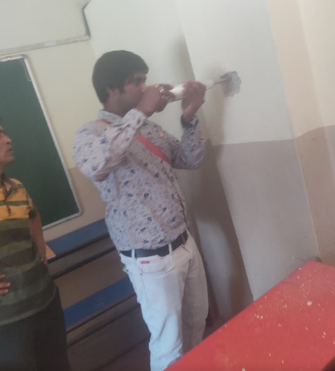
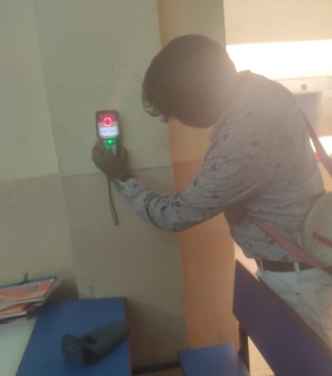
Testing photograph
rebound hammer
rcc test
Annexure 1
STRUCTURE ADEQUACY ANALYSIS
OF
BARASAT INDIRA GANDHI MEMORIAL HIGH SCHOOL AT
18, JESSOR Rd, BAROWARITOLA, BARASAT, KOLKATA, WEST BENGAL 700124
1. Method of structural adequacy analysis and design parameters:-
The seismic safety of a reinforced concrete building will depend upon the initial architectural and structural configuration of the total building, the quality of the Structural analysis, design and reinforcement detailing of the building frame to achieve stability of elements and their ductile performance under severe seismic lading. Proper quality of construction and stability of the infill walls and partitions are additional safety requirements of the structure as a whole. Any weakness left in the structure, whether in design or in construction will be fully revealed during the postulated maximum considered earthquake for the seismic zone 4 in the earthquake code IS: 1893.
Assumptions in static analysis
The basic assumptions in static analysis methodology are as follows:-
- The behavior of the structure is assumed to be perfectly linear and deformations are small
- All joints are rigid
- The members are subjected to axial, flexural and shear deformations
- The force deformation relationship remains linear during the entire load regime.
- Plinth beams are assumed
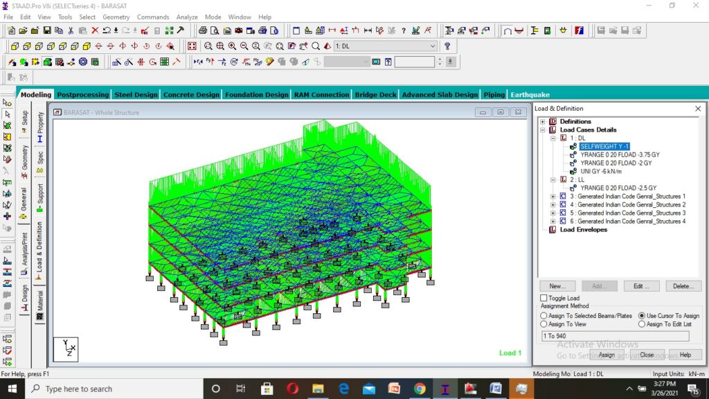
Mathematical Modeling
The structure is idolized as a 3-D space frame model. The beams and columns are considered as members. The floor slab load is given on beam members. The brick wall is used as a filler wall and is not casted monolithically with structure; hence this load is also given on beam members. The columns are assumed to be fixed at the foundation level.
2. Loads for Superstructure and Sub structural elements:
- Grade of Concrete: M23
- Steel: Fe415
- Slab thickness: 150mm
- Density of Concrete: 25kN/m³
- Density of Brick: 20kN/m³
- Live load on other floors: 3.5kN/m²,
- Live load on roof : 1.5 KN/m²,
- Floor Dead load: 5.5KN/m² (all dead load included in it like Tiles, False ceiling and others)
- Wall Load: 7KN/M(Excluding windows opening)
3. Seismic Moments and Forces in Frame Elements:
Seismic loads: As per I.S. 1893 – 2002 the discussed structure fall under earthquake zone 4.
Calculate the seismic moments and axial forces in the columns, shears and moments in the beams by using the seismic weights on the floors/ (column beam joints) through an appropriate computer software. It may be performed by Working Static load analysis. The important point is that according to IS: 1893 Cl.7.8.2.,
4. Materials properties data for static analysis: (as given in test certificates of reports; clause no 4.1)
1) Concrete
a) Concrete grade : Grade of concrete: M 23
b) Static modulus of elasticity Ec : 5000√fck
c) Poisson’s ratio : 0.17
d) Unit weight of R.C.C : 25 kN/m3
e) P.C.C : nominal mix of 1:4:8
2) Reinforcement Steel
Yield strength Fy : 415 N/mm2
Conforming to IS 1786 -1985
Static modulus of elasticity Es : 2 x 10⁵ N/mm2
5. Load combinations
Combination of Loads considered in analysis: The structural design has been carried out in accordance with the provisions of the codes IS 456 – 2000 and IS 1893 – 2002 for Normal design conditions
Table of Load combinations and load factors as per (Ref. IS: 456 – 2000, CI.18.2.3.1, 36.4.1, and B4.3)
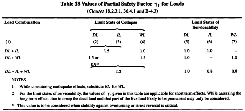
Note: DL = Dead Load, LL = Live Load/ Superimposed Load, WL = Wind Load, EL = Earthquake load
But in Analysis only working load 1.0 (DL+LL) is taken also material safety factor is removed from the analysis part
| BARASAT INDIRA GANDHI MEMORIAL HIGH SCHOOL AT18, JESSOR Rd, BAROWARITOLA, BARASAT, KOLKATA, WEST BENGAL,700124 Specification Used in Designing Process | ||||||||
| CALCULATIONS | ||||||||
| S.NO | PARTICULAR | SIZE OF (M) | GRADE OF CONCRETE | GRADE OF STEEL | STEEL AS PER SITE | STEEL AS PER STAAD | RESULT | |
| SQ.MM | SQ.MM | |||||||
| 1 | CENTERAL COLUMN | 0.23 | 0.40 | 23N/mm2 | 415N/mm2 | 800 | 1100 | UNSAFE |
| 2 | OUTER COLUMN | 0.23 | 0.23 | 23N/mm2 | 415N/mm2 | 1600 | 2900 | UNSAFE |
| 3 | OUTER BEAM | 0.23 | 0.3 | 23N/mm2 | 415N/mm2 | 804 | 950 | UNSAFE |
| 4 | INNER BEAM | 0.23 | 0.3 | 23N/mm2 | 415N/mm2 | 804 | 1100 | UNSAFE |
Leave a Reply