
PROJECT
8.46 m x 16.46 M COWS SHED (Conventional truss)
AT
NEAR ELECTRICAL SUB – STATION
KHASRA NO – 130 / 3
STRUCTURAL CONSULTANTS
O.B Developers
(STRUCTURE AUDIT AGENCY)
F 14, Kalkaji main road, new delhi-110019
mOB: +91-9717924616
Email; structureauditagency@gmail.com
WWW.STRUCTUREAUDITAGENCY.COM
- INTRODUCTION
The structure is a RCC + Steel(Truss) Framed Structure located at NEAR ELECTRICAL SUB – STATION
KHASRA NO – 130 / 3. In this report the design data sheet is attached along with the factor that are taken in account while analysis and design of the structure.
- VARIOUS CODE REFERED DURING ANALYSIS AND DESIGN
- IS 456
- IS 875
- IS 1893
- IS 800
2. aNALYSIS AND DESIGN DATA
2.1 Method of structural adequacy analysis and design parameters
The seismic safety of a multi-storeyed reinforced steel building will depend upon the initial architectural and structural configuration of the entire building. The methodology of the Structural analysis, design and detailing of the structural framework will be resorted to achieve stability in each aspect and its ductile performance under severe seismic lading. Due consideration should be given to the aspect of fabrication and connection. Any weakness, if left in the structure, either in the design or in the fabrication will be fully reflected during the postulated design seismic loading for the seismic zone in the earthquake code IS: 1893 Part IV.
- Assumptions in static analysis
The basic assumptions in static analysis methodology are as follows:-
- The behaviour of the structure is assumed to be perfectly linear and deformations are small
- All joints are rigid
- The members are subjected to axial, flexural and shear deformations
- The force deformation relationship remains linear during the entire load regime.
- Most critical section of building is selected for analysis where building section has soft storey
- Mathematical Modelling
The structure is idealized as a 3-D space frame model. The beams and columns are modelled as flexural members. The columns are idealized to be pinned at the foundation level.
2.2 Loads for Superstructure and Sub structural elements:
- Steel : Fe250
- Density of Steel : 78kN/m³
- Self-weight factor : 1.0(Including Weight of paint, rusting etc.)
- Wall load : 5kN/m
- Live Load : 0.5kN/Sqm (Human Load in Future for Repair and Sheet Load)
- Wind speed :47 m/sec (As per IS 875-Part 3)
- Wind Pressure :1.325 KN/m2
2.3 Materials properties data for static analysis
- Steel Sections
Conforming to IS 808 -1989
Yield strength Fy : 250 N/mm2
Static modulus of elasticity Es : 2 x 10⁵ N/mm2
2.4 Load Factors for Plastic Design of Steel Structures
Combination of Loads considered in analysis: The structural design has been carried out in accordance with the provisions of the codes IS: 1893(Part-I) for Normal design conditions
In the plastic design of steel structures, the following load combinations shall be accounted for:
a) 1.7 (DL + IL),
b) 1.7 (DL + IL) + WL, and
c) 1.3 (DL + IL + WL)
2.5 Materials properties data for static analysis: (as given in test certificates of reports; clause no 4.1)
1) Concrete
a) Concrete grade : Grade of concrete: M25(1:1:2)
b) Static modulus of elasticity Ec : 5000√fck
c) Poisson’s ratio : 0.2
d) Unit weight of R.C.C : 25 kN/m3
e) P.C.C : nominal mix of 1:4:8
2) Reinforcement Steel
Yield strength Fy : 500 N/mm2
Conforming to IS 1786 -1985
Static modulus of elasticity Es : 2 x 10⁵ N/mm2
2.6 Geotechnical Considérations
The foundation design is based on the geotechnical recommandations outlined in the “Geo- Technical Investigations report.
2.6.1 Suitable Foundation :
The foundation system adopted is Isolated as per soil report recommandations.
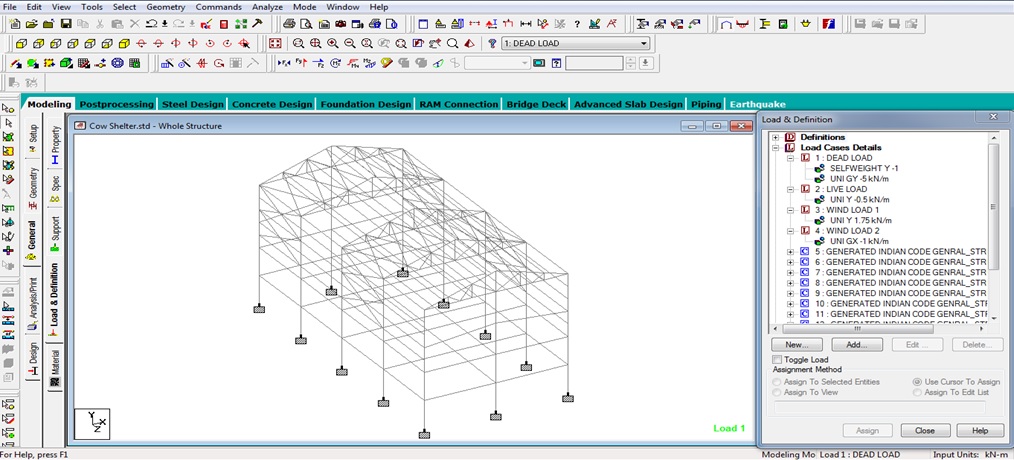
3. Structure Adequacy analysis in Staad Pro.
- Seismic Moments and Forces in Frame Elements:
Wind loads: As per IS 875
Calculate the moments and axial forces in the columns, shears and moments in the beams by using the seismic weights on the floors/ (column beam joints) through an appropriate computer software. It may be performed by Response Spectrum or Time History analysis.
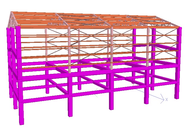
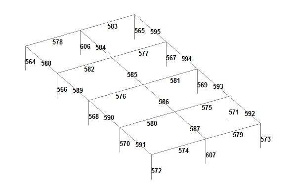
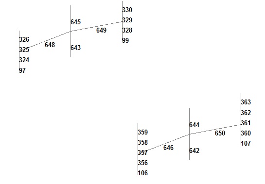
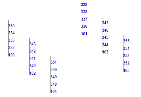
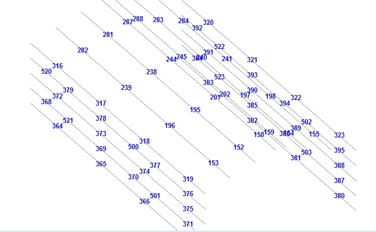
3D View
|
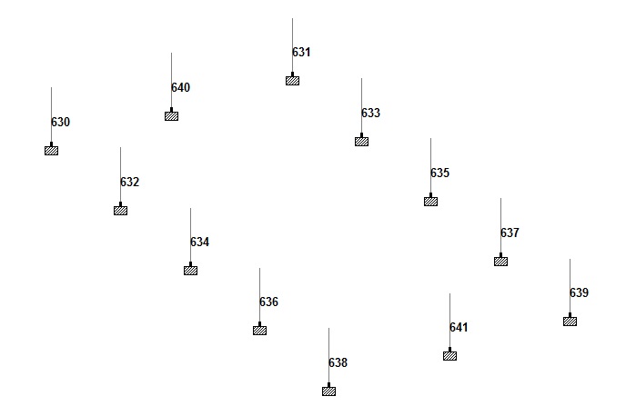
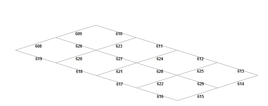
| Staad Pro Grid Marking | |
| Grid Marking | Suitable Section Size and Details |
 Column Below Tie Beam Column Below Tie Beam | Suitable column size is 300mmx300mm with 6 bars 16mm diameter+2 bars 12mm diameter. Rings should be 8mm diameter and 75mm spacing c/c. |
 Tie Beam Tie Beam | Suitable Tie Beam size is 230mmx230mm with 3 bars 12mm diameter at top and 3 bars 16mm diameter at bottom. Rings should be 8mm diameter with spacing is 150mm c/c |
 Plinth Level Column and Plinth Beam Plinth Level Column and Plinth Beam | Suitable column size is 300mmx300mm with 6 bars 16mm diameter+2 bars 12mm diameter. Rings should be 8mm diameter and 75mm spacing c/c. Suitable Plinth Beam size is 300mmx300mm with 3 bars 16mm diameter at top and 3 bars 16mm diameter at bottom. Rings should be 8mm diameter with spacing is 150mm c/c |
 Column and Beam above Plinth Level Column and Beam above Plinth Level | Suitable column size is 300mmx300mm with 6 bars 16mm diameter+2 bars 12mm diameter. Rings should be 8mm diameter and 75mm spacing c/c. Suitable Beam size is 300mmx300mm with 3 bars 16mm diameter at top and 3 bars 16mm diameter at bottom. Rings should be 8mm diameter with spacing is 150mm c/c |
 Steel Columns Steel Columns | Steel column should be a tube 150mmx150mmx6mm thickness. With a base plate of 300mmx300mm and 16mm thickness with 4 anchors bolts 16mm diameter and 900mm+150mm length. Top plate 300mmx300mmx16mm |
 Top and Side Purlins Top and Side Purlins | Purlin suitable size is ISMC 200 |
 Top and Bottom Rafter Top and Bottom Rafter | Rafter suitable size is tube 125mmx125mmx5mm thickness |
 Secondary Members Secondary Members | Secondary members suitable size is tube 50mmx50mmx4mm thickness |
 Bracing Layout Bracing Layout | Suitable bracing are pipe 34mm diameter and 3mm thickness |
Leave a Reply