
STRUCTURAL AUDIT REPORT
REPORT NAME : STRUCTURE STABILITY ANALYSIS
PROJECT LOCATION : Pit A, B & C
STRUCTURAL CONSULTANTS
O.B Developers
(STRUCTURE AUDIT AGENCY)
F-14, Kalkaji main road
new delhi-110019
MOB: +91-9717924616
structureauditagency@gmail.com
WWW.STRUCTUREAUDITAGENCY.COM
- INTRODUCTION
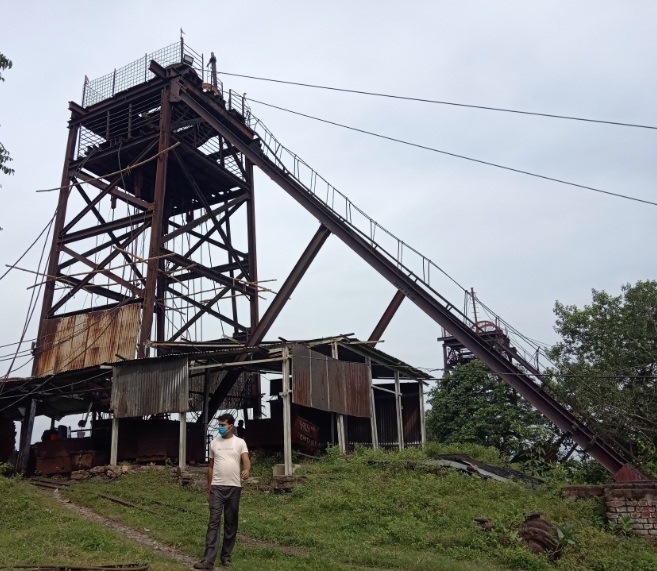
The structure is a Steel Stack Industrial Structure located at xxxxxx. In this report the design datasheet is attached along with various factors that are taken into account while analysis and design of the structure.
- VARIOUS CODE REFERED DURING ANALYSIS AND DESIGN
(i) IS 800
(ii) IS: 1893
(iii) IS 875
2.ANALYSIS AND DESIGN DATA
2.1 Method of structural adequacy analysis and design parameters
The seismic safety of a multi-storeyed reinforced steel building will depend upon the initial architectural and structural configuration of the entire building. The methodology of the Structural analysis, design and detailing of the structural frame work will be resorted to achieve stability in each aspect and its ductile performance under severe seismic lading. Due consideration should be given to the aspect of fabrication and connection. Any weakness, if left in the structure, either in the design or in the fabrication will be fully reflected during the postulated design seismic loading for the seismic zone in the earthquake code IS: 1893 Part IV.
- Assumptions in static analysis
The basic assumptions in static analysis methodology are as follows:-
- The behaviour of the structure is assumed to be perfectly linear and deformations are small
- All joints are rigid
- The members are subjected to axial, flexural and shear deformations
- The force deformation relationship remains linear during the entire load regime.
- Most critical section of building is selected for analysis where building section has soft storey
- Mathematical Modelling
The structure is idealized as a 3-D space frame model. The beams and columns are modelled as flexural members. The columns are idealized to be pinned at the foundation level.
2.2 Loads for Superstructure and Sub structural elements:
- Steel : Fe250
- Density of Steel : 78kN/m³
- Self weight factor : 1.5( Including Weight of paint, rusting etc.)
- Dead load : 5kN (Maximum load which pulley can carry/Rope Breaking Load)
- Live Load : 10kN/m2 (Thrust load while engine starts/Movement load/Dynamic Load)
- Wind speed : 47m/sec (As per IS875-Part-3)
- Wind Pressure : 1.325 KN/m2
2.3 Materials properties data for static analysis
- Steel Sections
Conforming to IS 808 -1989
Yield strength Fy : 250 N/mm2
Static modulus of elasticity Es : 2 x 10⁵ N/mm2
2.4 Load Factors for Plastic Design of Steel Structures
Combination of Loads considered in analysis: The structural design has been carried out in accordance with the provisions of the codes IS: 1893(Part-I) for Normal design conditions
In the plastic design of steel structures, the following load combinations shall be accounted for:
a) 1.7 (DL + SIDL + IL),
b) 1.7 (DL + SIDL) + EL, and
c) 1.3 (DL + SIDL + IL + EL)
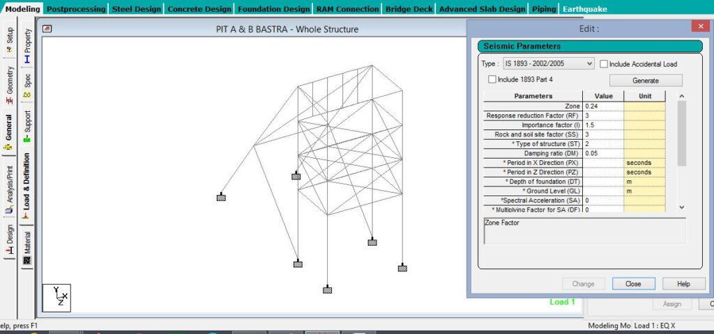
Fig. 2.1 Seismic Definition of xx PIT A,B&C conforming site condition
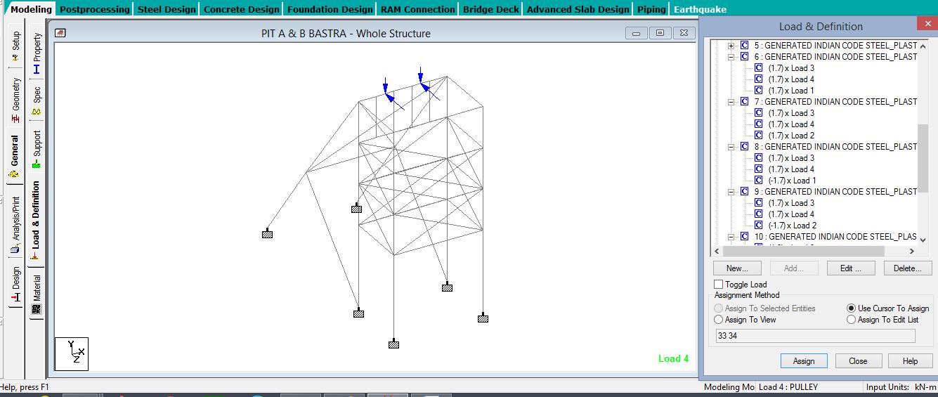
Fig. 2.2 Static/Wind/Rope Braking calculated Load calculated for the analysis of xxxx PIT A,B&C conforming site condition
- SUMMARY OFMEMBER Adequacy Analysis in Staad.Pro
3.1 MEMBER ADEQUACY FOR PIT A
| Blue members 1<utility ratio <1.2 Red Members utility ratio >1.2 |
Utility ratio means member load carrying capacity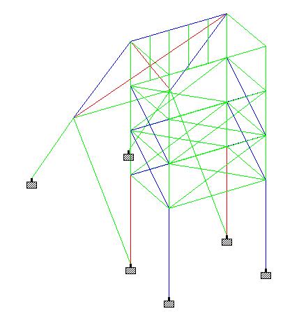
| Fig 3.1 Utility Ratio Representation of Members of xxxxx PIT A before retrofit |
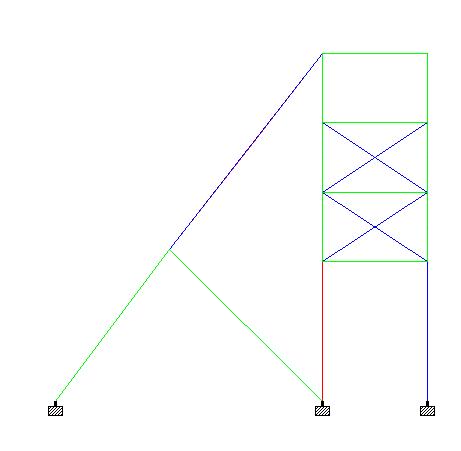
| Fig 3.2 Utility Ratio Representation of Members of xxxPIT A after retrofit |
| S.No | Analysis Result as per IS 800, IS 875, IS 1893 | Recommendations | Retrofitting Details |
| 1 | Bracing members provided along Grid C1&C2And between grid A& B level 1&3 i.e. ISMC 200 have been found to have utility ratio above 1.2 | All such member having utility ratio above 1.2 should be replaced by member having utility ratio less 1.2 As per actual stresses developed in worst condition as per IS800, IS875, IS1893 the member Strength is found to be unsafe for loading. | ISMC 200 replaced by ISMC 350 |
| 2 11 | ISHB 250 provided along Grid A and B at bottom level(column) have been found to have utility ratio above 1.2 | ISHB 250 Beam should be provided with ISMC 300 place over the top and bottom of ISHB 250 beam in a way that the flange of ISMC 300 should face toward web of ISHB 250 | |
3-D RENDERED PERSPECTIVE OF THE MODEL 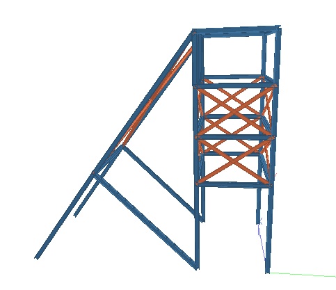 Fig 4.1 Rendered Perspective of Model of xxx PIT A Fig 4.2 Rendered Front Perspective of Model of xxxx PIT A 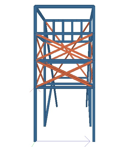 Fig 4.4 Rendered Side Perspective of Model of xxxPIT A | |||
Leave a Reply