
STRUCTURAL AUDIT REPORT
PROJECT NAME : ANALYSIS of EXISTING CNG PUMP CANOPY
PROJECT LOCATION : SONIPAT, HARYANA
STRUCTURAL CONSULTANTS
O.B Developers
(STRUCTURE AUDIT AGENCY)
F-14, Kalkaji main road
new delhi-110019
MOB: +91-9717924616
structureauditagency@gmail.com
WWW.STRUCTUREAUDITAGENCY.COM
- INTRODUCTION
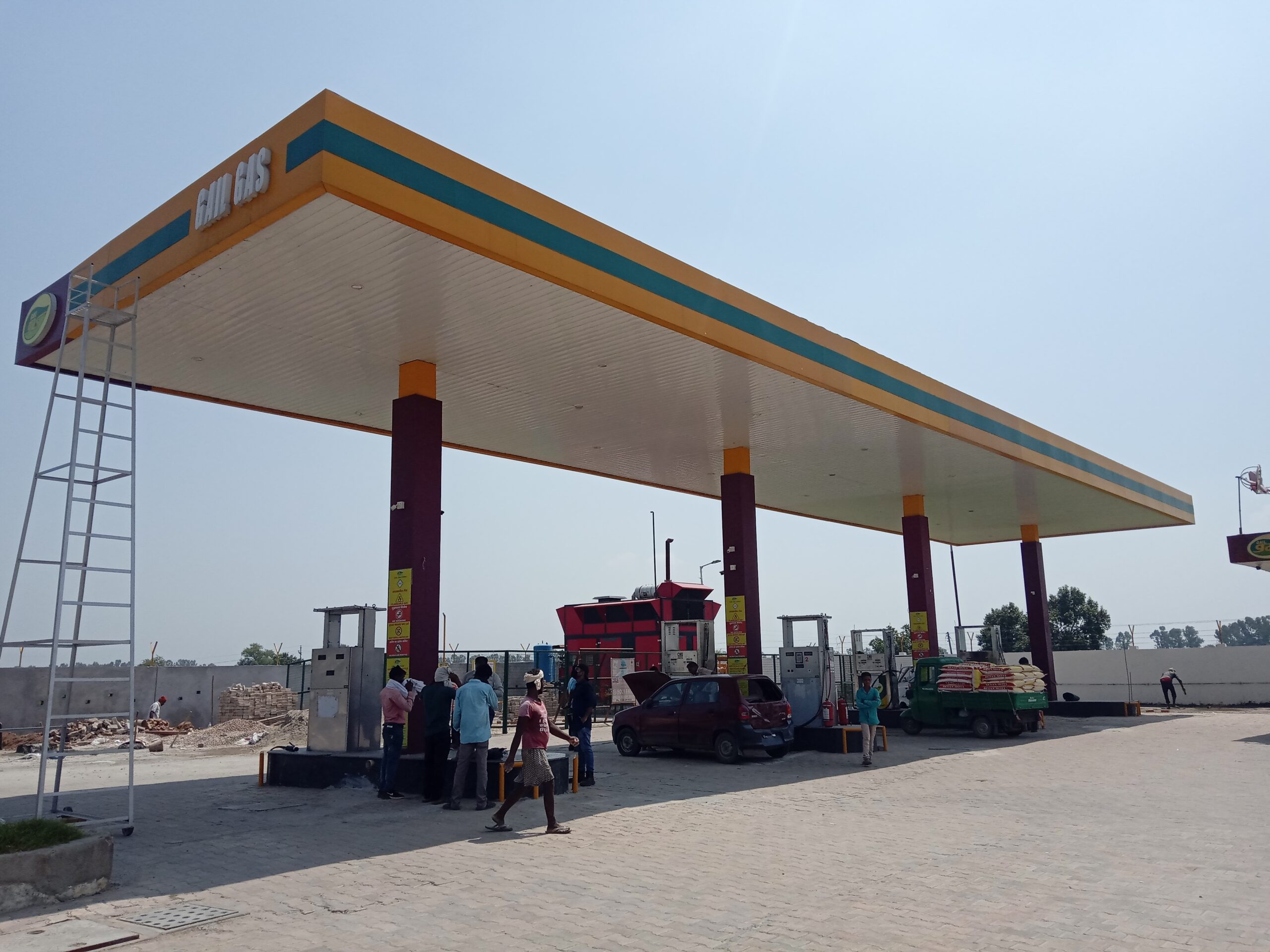
The structure is a CNG FILLING STATION CANOPY located at SONIPAT, HARYANA. In this report the design data sheet is attached along with various factors that are taken into account while analysis and design of the structure.
- VARIOUS CODE REFERED DURING ANALYSIS AND DESIGN
(i) IS 800
(ii) IS 875
- AUDIT WORK DONE AT SITE.
- As Built Drawings Preparation
- Thickness Reduction Test / Corrosion Impact Test
As per the NDT test we found that the members are suffering from corrosion which leads to reduction of 1.5mm thickness in structural members as per corrosion impact test.
- SUMMARY OF STABILITY ANALYSIS
- Over all the structure is found to be unsafe and retrofitting is needed
- Apart from retrofitting the rust from the existing members need to be removed and an anti-corrosion paint need to be applied over it.
ANALYSIS AND DESIGN DATA
FOR
CNG PUMP
2.1 Method of structural adequacy analysis and design parameters
The safety of a Canopy Structure against WIND will depend upon the architectural and structural configuration of the entire canopy, its location and exposure to wind. The methodology of the Structural analysis, design and detailing of the structural framework will be aimed to achieve stability in each aspect and its satisfactory performance under wind lading. Due consideration has been given to the aspect of fabrication and connection. Any weakness, if left in the structure, either in the design or in the fabrication will be fully reflected during the postulated design wind loading for the wind zone in the earthquake code IS: 875 Part III.
- Assumptions in static analysis
The basic assumptions in static analysis methodology are as follows:-
- The behaviour of the structure is assumed to be perfectly linear and deformations are small
- All joints are rigid
- The members are subjected to axial, flexural and shear deformations
- The force deformation relationship remains linear during the entire load regime.
- Most critical LOAD COMBINATION has been assigned to assess it utility and retrofitting.
- Mathematical Modelling
The structure is idealized as a 3-D space frame model. The beams and columns are modelled as trussed structure. The columns are idealized to be fixed at the foundation level.
2.2 Loads for Superstructure and Sub structural elements:
- Steel : Fe250
- Density of Steel : 78kN/m³
- Self weight factor : 1
- Terrain Category : 2
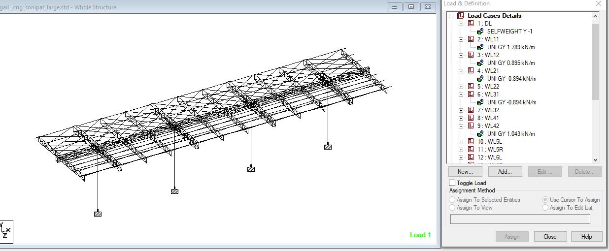
- Wind Pressure on the purlins :1.788 kN/m
2.3 Materials properties data for static analysis
- Steel Sections
Conforming to IS 808 -1989
Yield strength Fy : 250 N/mm2
Static modulus of elasticity Es : 2 x 10⁵ N/mm2
2.4 Load Factors for Plastic Design of Steel Structures
Combination of Loads considered in analysis: The structural design has been carried out in accordance with the provisions of the codes IS: 800-2007 for plastic design of steel structures, whereas IS: 875(Part-III) has been used to calculate design wind pressure on purlins.
In the plastic design of steel structures, the following load combinations shall be accounted for:
- 1.5 (DL+ WL) (for limit state of strength)
- 1.0(DL+ WL) (for limit state of serviceability)
Fig. 2.1 Loading on the Canopy Model conforming Codal Provisions
Fig. 2.2 Load combination used in the analysis of the Canopy Model conforming to IS: 800-2007
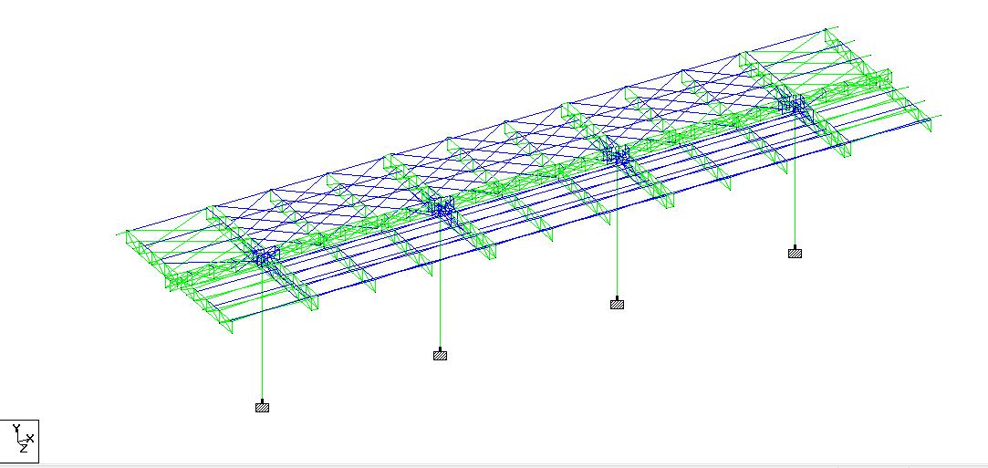
- SUMMARY OF MEMBER adequacy analysis in Staad.Pro
| Blue members 1<utility ratio <1.2 Red Members utility ratio >1.2 |
MEMBER ADEQUACY FOR LARGE FILLING STATION
3.1.1 RESULTS AND DISCUSSION
| S.No | Analysis Result as per IS 800, IS 875, IS 1893 | Recommendations | Retrofitting Details |
| 1. | ISMC 75 member provided as PURLIN have been found to have utility ratio above 1.2. Refer Fig. 3.1.3 | All such member having utility ratio above 1.2 should be replaced by member having utility ratio less 1.2 | ISMC 75 Purlin in the Cantilever portion of Canopy have been replaced by ISMC 125 Refer Fig. 3.1.5 |
| 212 | ISA 75x75x8 provided in the Ridge Beam Truss along the Canopy have been found to have utility ratio above 1.2 .Refer Fig. 3.1.4 | All such member having utility ratio above 1.2 should be replaced by member having utility ratio less 1.2 | ISA 65x65x8 member size has been provided as diagonal bracing in the Ridge Beam Truss in addition to diagonal bracing present already Refer Fig. 3.1.6 |
| 3 3. | Deflection at various location were far beyond the Permissible deflection as provided in IS:800-2007 Refer Fig 3.1.9 | Retrofitting is recommended | In order to control the deflection at such location typical diagonal bracings have been provided :- ISA 110x110x8 have been provided in plan form at Cantilever Panels. Refer Fig. 3.1.7At Panels other than Cantilever Panel ISA 75x75x8 have been provided in plan form. Refer Fig 3.1.8 |
| 4. | Rotation at the junction of column and truss beam carrying purlins is severe. Refer Fig 3.1.9 | Retrofitting is recommended | ISMC 300 @300 C/C has been provided on the both sides to tie down the beams supporting purlins to column, eventually adding stiffness in the plane of rotation. Refer Fig.3.1.10 |
3.1.2 MEMBER UTILITY DETAILED REPRESENTATION 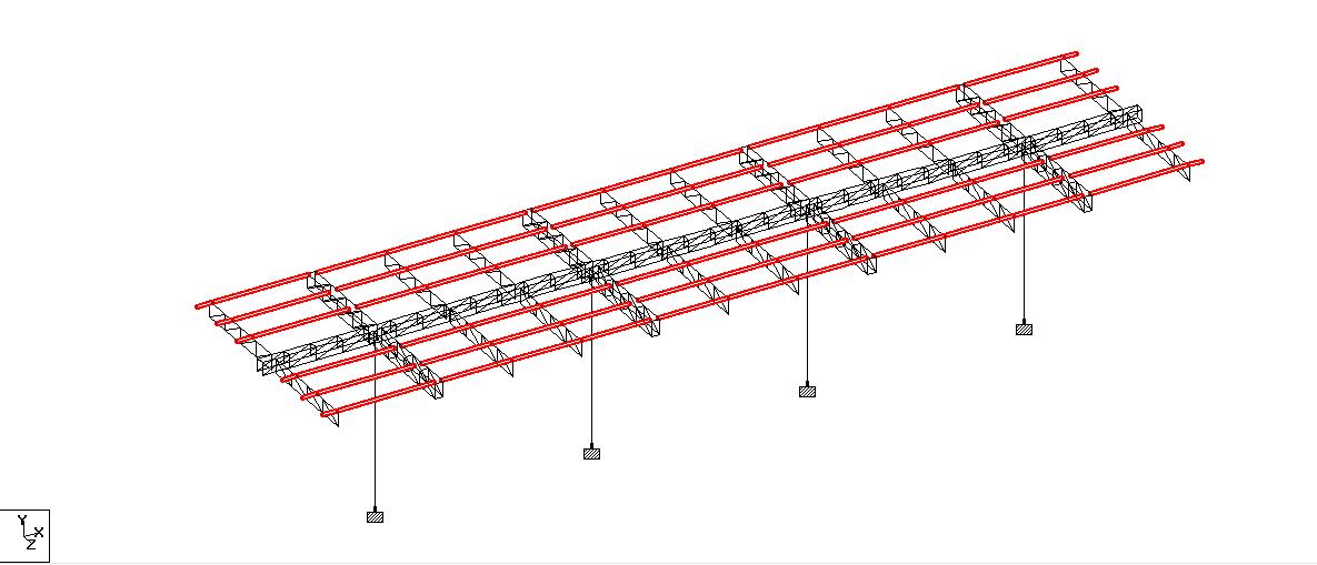 Fig. 3.1.3 ISMC 75 member provided as PURLIN having utility ratio above 1.2 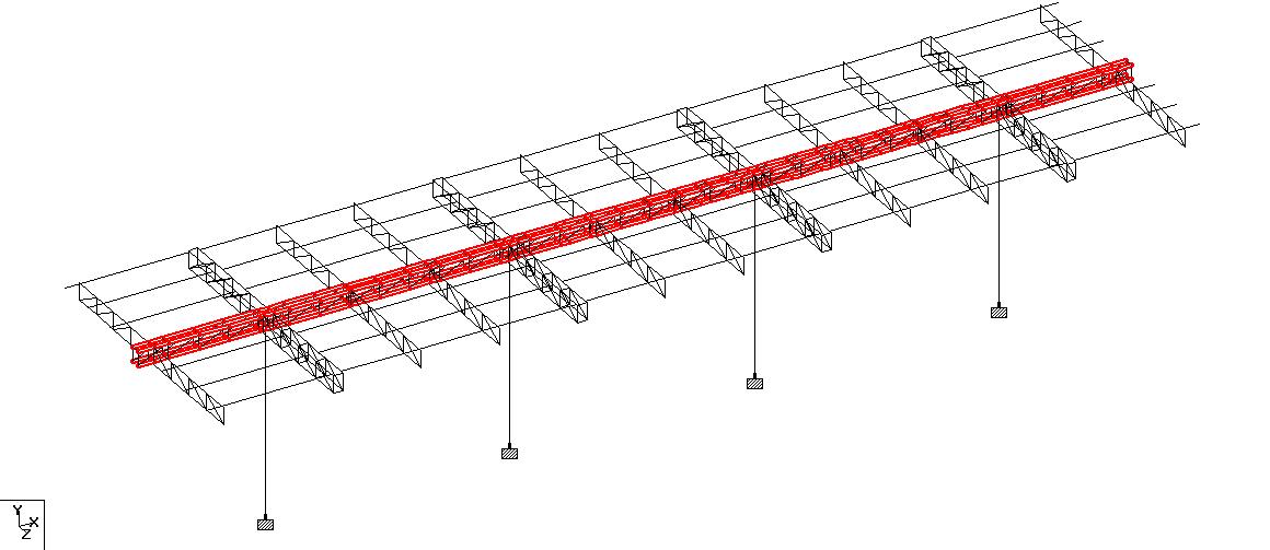 Fig. 3.1.4 ISA 75x75x8 provided in the Ridge Beam Truss along the Canopy having utility ratio above 1.2 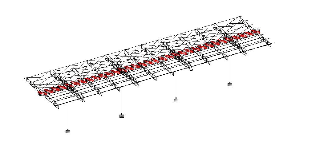 Fig 3.1.5 ISMC 75 Purlin in the Cantilever portion of Canopy have been replaced by ISMC 125 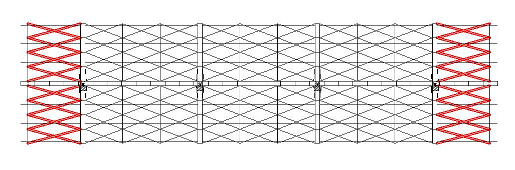 Fig 3.1.6 ISA 65x65x8 member size has been provided as diagonal bracing in the Ridge Beam Truss in addition to diagonal bracing present already 3.1.3 RETROFTTING DETAILED REPRESENTATION 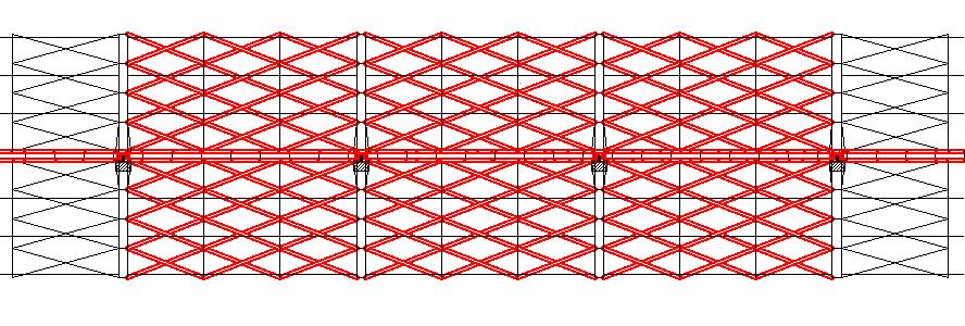 Fig 3.1.8 ISA 75x75x8 provided in plan form Fig 3.1.7 ISA 110x110x8 provided in plan form Fig 3.1.8 ISA 75x75x8 provided in plan form Fig 3.1.7 ISA 110x110x8 provided in plan form 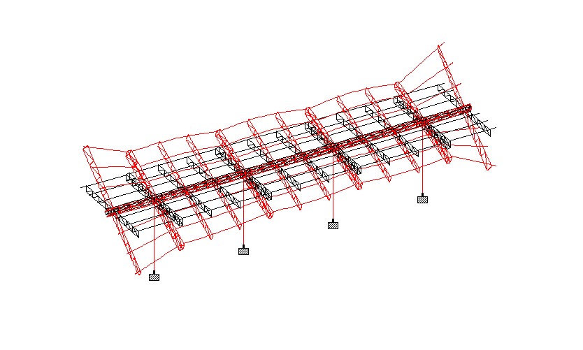 Fig 3.1.9 Deflection diagram of structure at severe Load Combinationmbefore retrofit Fig 3.1.10 ISMC 300 @300 C/C provided to control rotation ISMC 300 Fig 3.1.11 Deflection diagram of structure at severe Load Combination after retrofit 3.1.4 3-D RENDERED PERSPECTIVE OF THE MODEL 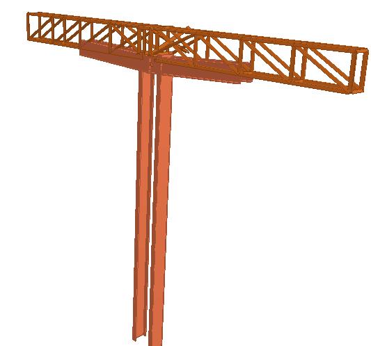 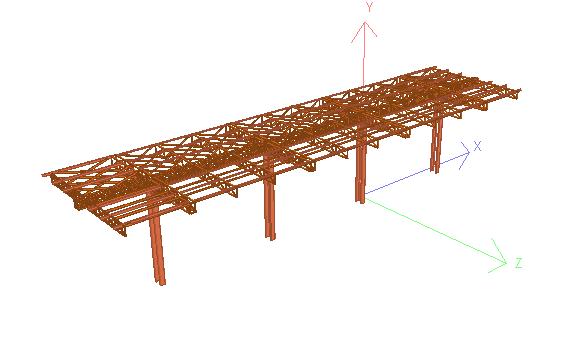 Fig 3..1.12 Rendered Perspective of Model of Large Filling Station | |||
Leave a Reply