
AT
517, SECTOR-21C FARIDABAD, HARYANA
For
M/s U.S. ASSOCIATE
Prepared By:-
O.B DEVELOPERS
(STRUCTURE AUDIT AGENCY)
Email- strutureauditagency@gmail.com
Call-+91-9717924616
www.structureauditagency.com
Executive Summary:
Based on the Visual Inspection & NDT Results
Of all the Structural Members of the Existing Building
- In order to assess the structural stability of the building, following tests were conducted at site
- Rebound Hammer Test as per IS: 13311 (Part-2)-1992 for determining the estimated compressive strength and uniformity of concrete in terms of surface hardness test
- Cover Meter Test as per IS 456:2000 to measure the clear cover of structure members.
- Structural section detailing: Preparation of structural drawings by using proof-meter, Profometer for measuring the cover depth and existing protecting layer of steel rebar, diameter of steel and number of rebar for beam column frame system only. Profometer test to ascertain the location & spacing of the rebars and cover of concrete provided to the rebars as per code BS1881; 204. We have done independent cross check of steel rebar and section details of RCC sections. In addition to above, the concrete covers of the RCC members were removed to expose the rebars to physically verify. Our results obtained from proof-meter test are tallying with the results available at exposed RCC sections.
- Estimated strength is based rebound hammer values. Statistical data shows that dominating percentage of quality of concrete is in the range of M15 for all types of RCC sections. Concrete surfaces are not suffering from surface hardness problem and there are no indications of blistering of concrete surface as per IS 13311 (Part-2)-1992. Structure has variable pattern of concrete quality in terms of surface hardness
- Brick Compressive Strength: To check the compressive strength of burnt brick as per IS 3495 :1992 part I, IS 1077 : 1992
- Summary for structural adequacy analysis
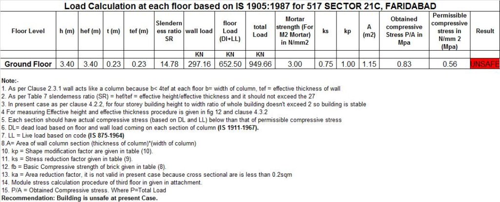
- The structure is safe for loading for dead and live load only up to G+2 only. Unsafe for loading in earthquake forces (wall thickness are insufficient).
Table of Contents
| Sr.No. | Description of NDT Reports | Page No. | |
| 1 | Introduction, Scope of Work | 4-6 | |
| 2 | Methodology For Performing Non-Destructive Tests | 7-8 | |
| 3 | NDT Test Results & Interpretation | ||
| 3.1 | Rebound Hammer Test Results & Interpretation | 9 | |
| 3.2 | Structure drawing preparation by Profo-scope | 10 | |
| 3.3 | Brick and Mortar Test Results & Interpretation | 11-13 | |
| 4 | Annexure 1 -Marked Test Location -Relevant Testing Code -Structure Adequacy Analysis | ||
1. Introduction
- Introduction
The existing structure at Faridabad, Haryana is a ground floor masonry structure. M/s U.S. Associate awarded the work to M/s O.B Developers for conducting condition assessment of masonry structures using Non-destructive testing.
This report pertains to the asserted safety appraisal and structural health assessments standards. In this report description of the damaged portions of the building, objectives of the investigation and survey, general methodology and test procedures etc. are given, followed by details of the observations recorded at the site and results of in-situ and laboratory tests.
1.2. Walkover survey and visual inspection
First and foremost activity in a condition survey and structural investigation, especially in distressed building, is a walk over survey or systematic visual inspection so as to gather readily available information about the structure in question.
The visual observations and documentation was made for the RCC structures to determine if there are any obvious signs of distress, deflection or deterioration in the structure. Based on the visual inspection, redistribution of the number of tests to be performed as per the scope of work and their point of conductance were proposed so as to confirm the recommendations and findings of visual inspection.
1.3. Objectives of the overall investigation
The overall objective of the investigation carried out for the structure is to obtain an up to date account of the health condition of the structure so that appropriate repair measures can be taken up to make up for the damages sustained. Keeping this in view the basic objectives of the investigation formulated is as given below.
- To assess the existing condition of the structural elements.
- To determine the extent of damages in the structure, so as to undertake suitable remedial measures for rehabilitation of the structure.
1.4 Scope of work and selection of tests
In-situ tests and laboratory tests have been selected based on the visual inspections carried out and as detailed in the scope of work. The selection of tests has been done so as to meet the overall objective of the NDT study and the observations made during a quick walk over survey. Various Tests were conducted for the evaluation of the Structure:
The various Non-Destructive Tests carried out for health assessment and structural audit of the RCC structures are given below
.
- Rebound Hammer Test: For determining the estimated compressive strength of concrete and uniformity of concrete in terms of surface hardness as per IS 13311 (Part-2)-1992.
- Cover Meter Test: Conducting cover meter test at selected locations on RCC members of the structures covered under the study to see the adequacy of concrete cover to rebars and effect of carbonation.
- Structural Drawings Preparation: Preparation of structural drawings with complete RCC details, section sizes and steel percentage by using profometer or GPR based scanner, it will give detailed cover depth and existing protecting layer of steel rebar, diameter of steel and number of steel bar.
- Structure Analysis: To Analysis the maximum load that roof slab can carry safely as per IS 456:2000,IS 1893, IS 1905,IS 875 and SP 16 in Seismic Zone 4.
- Brick Compressive Strength: To check the compressive strength of burnt brick as per IS 3495 :1992 part I, IS 1077 : 1992
2. TESTING PROCEDURE
2.1 Rebound Hammer Test:-
Purpose:-
This test gives a measure of the surface hardness of the concrete surface. Although there is no direct relationship between this measurement of surface hardness and strength, an empirical relationship exists.
Objective of testing:-
Rebound hammer test is performed to determine the following:
- Surface hardness
- Uniformity of concrete
- Quality of concrete in respect to standard requirements and comparative analysis
- Estimated strength which is derived from establishing a relationship between in-situ core strength and rebound index.
References:-
- BS 6089:1981 and BS 1881:Part 202,
- IS13311(Part2):1992
- ASTM C 805-02
- BS EN13791:2007
Influencing factors:-
Rebound hammer test results are considerably influenced by these factors:
- Size, shape and rigidity of the specimen
- Age of test specimen
- Smoothness of surface and internal moisture condition of the concrete
- Carbonation of concrete surface
Testing Method:-
According to ASTM C 805-02 clause 7.1 the concrete members to be tested shall be at least 100mm thick and fixed within a structure. Trowelled surfaces generally exhibit high rebound numbers than screed or formed finishes. Do not compare the test results if the form material against which the concrete is placed is not similar. Heavily textured, soft or surfaces with loose mortar shall be ground flat with abrasive stone. Smooth formed or trowelled surfaces do not have to be ground prior to testing. Also this test is not conducted directly over the reinforcing bars having cover less than 20mm. The surface under test should be clean and smooth because rough surfaces cannot be tested as they do not give reliable results. Dirt or other loose material on the surface can be removed using a grinding stone prior to test.
3.1 Test Certificate:- Rebound Hammer TEST
| Quality Assurance in Concrete using Non Destructive Testing | |||||||||||
| Client:- US Associate | Consultant :- OB Developers | ||||||||||
| Non Destructive Testing at 517,SEC -21C, FARIDABAD HARYANA | |||||||||||
| S. No./Location | Rebound Hammer Test | ||||||||||
| SL. No. | Sample Identification/ Location | Hammer Alignment | Rebound No. | Avg. Rebound No. | Quality Of Concrete | Estimated Concrete Strength N/mm2 | |||||
| Ground floor | |||||||||||
| 1 | SLAB | Vertical UP | 32 | 32 | 32 | 34 | 32 | 34 | 33 | Good Layer | 18.10 |
| 2 | SLAB | Vertical UP | 32 | 34 | 32 | 34 | 32 | 34 | 33 | Good Layer | 18.35 |
| 3 | SLAB | Vertical UP | 34 | 32 | 34 | 34 | 32 | 34 | 33 | Good Layer | 18.60 |
| 4 | SLAB | Vertical UP | 34 | 32 | 34 | 34 | 32 | 34 | 33 | Good Layer | 18.60 |
| 5 | SLAB | Vertical UP | 34 | 32 | 34 | 32 | 34 | 32 | 33 | Good Layer | 18.35 |
| 6 | SLAB | Vertical UP | 34 | 32 | 33 | 34 | 34 | 32 | 33 | Good Layer | 18.47 |
| 7 | SLAB | Vertical UP | 34 | 33 | 32 | 32 | 30 | 32 | 39 | Good Layer | 22.78 |
| 8 | COLUMN | Horizontal | 28 | 26 | 24 | 22 | 24 | 28 | 25 | Fair | 12.69 |
| 9 | COLUMN | Horizontal | 26 | 24 | 26 | 28 | 24 | 26 | 26 | Fair | 12.94 |
| 10 | COLUMN | Horizontal | 28 | 30 | 28 | 30 | 28 | 28 | 29 | Fair | 15.15 |
| Rebound Hammer(ASTM C 805- 85):- Surface Hardness indices value should be more than 28 to get correlation with estimated strength , uniformity of concrete |
INTERPRETATION OF RCC SURFACE CONDITION, UNIFORMITY OF CONCRETE AND FCK VALUE OF CONCRETE OBTAINED FROM REBOUND HAMMER:-
A .Test results analysis of the Rebound Number values is based on test results conducted over concrete surfaces. Obtained test results explain about pattern of concrete quality of whole structure sections in terms of surface hardness. Statistical data shows that dominating percentage of quality of concrete is in range of M15. Concrete surfaces are not suffering from surface hardness problem. There is also no indication of blistering of concrete surface as per IS 13311 (Part-2)-1992. Estimated strength is based rebound hammer values. Statistical data shows that dominating percentage of quality of concrete is in the range of M15 for all types of RCC sections.
3.2. Structural Drawing preparation by
using PROFOSCOPE
- Column C1- 230mmx230mm with 4 nos bars 12mm diameter & 8mm diameter rings spacing 150mmc/c, Cover-40mm to 55mm.Column C2- 300mmx300mm with 4 nos bars 12mm diameter & 8mm diameter rings spacing 150mmc/c, Cover-45mm to 50mm.
- Slab 150mm thickness with 8mm bar @150mm c/c,cover-20mm to 30mm.
3.3. Brick & mortar test Results
3.3.1 Brick Test:-
| Test as per : IS 3495 :1992 part I, IS 1077 : 1992 , ASTM C 67 | |||||
| Non Destructive Testing at 517,SEC -21C, FARIDABAD HARYANA | |||||
| Client:- US Associate | Consultant :- OB Developers | ||||
| Sr. No. | Sample Identification | Dimension mm/mm | Loading surface area m2 | Failure load kN | Result MPa (As per : IS 3495 :1992 part I, IS 1077 : 1992) |
| Ground Floor | |||||
| 1 | Brick Sample 1 | (230)*(110)*(70) | 0.0242 | 167.7 | 6.9 |
3.3.2 Mortar test: – Chemical analysis of mortar for cement/lime percentage as per ASTM C 1084-97
| Serial | Location nomenclature | cement % in binding mortar (average of three samples) | Sand % | Type of mortar |
| 1 | Wall of Room | 18% | 82% | M2 |
3.3.3 Summary of In-situ strength of masonry building components for structural adequacy analysis
| Table 1 Mix Proportion and Strength of Mortars for Masonry | |||||||
| (Clause 3.2.1) 1905:1984 | |||||||
| S.No. | Grade of MORTAR | Mix Proportions (By Loose Volume) | Min. Compressive Strength at 28 days in N/mm2 | ||||
| Cement | Lime | Lime Pozzolana Mixture | Pozzolana | Sand | |||
| 1 | 2 | 3 | 4 | 5 | 6 | 7 | 8 |
| 1 | H1 | 1 | ¼C or B | 0 | 0 | 3 | 10 |
| 2(a) | H2 | 1 | ¼C or B | 0 | 0 | 4 | 7.5 |
| 2(b) | 1 | ½C or B | 0 | 0 | 4½ | 6 | |
| 3(a) | M1 | 1 | 1 C or B | 0 | 0 | 5 | 5 |
| 3(b) | 1 | 0 | 0 | 0 | 6 | 3 | |
| 3(c) | 0 | 1(LP-40) | 0 | 1½ | 3 | ||
| 4(a) | M2 | 1 | 0 | 0 | 0 | 6 | 3 |
| 4(b) | 1 | 2B | 0 | 0 | 9 | 2 | |
| 4(c) | 0 | 1A | 0 | 0 | 2 | 2 | |
| 4(d) | 0 | 1B | 0 | 1 | 1 | 2 | |
| 4(e) | 0 | 1 C or B | 0 | 2 | 0 | 2 | |
| 4(f) | 0 | 0 | 1(LP-40) | 0 | 1¾ | 2 | |
| 5(a) | M3 | 1 | 0 | 0 | 0 | 7 | 1.5 |
| 5(b) | 1 | 3B | 0 | 0 | 12 | 1.5 | |
| 5(c) | 0 | 1A | 0 | 0 | 3 | 1.5 | |
| 5(d) | 0 | 1B | 0 | 2 | 1 | 1.5 | |
| 5(e) | 0 | 1C or B | 0 | 3 | 0 | 1.5 | |
| 5(f) | 0 | 0 | 1(LP-40) | 0 | 2 | 1.5 | |
| 6(a) | L1 | 1 | 0 | 0 | 0 | 8 | 0.7 |
| 6(b) | 0 | 1 B | 0 | 1 | 2 | 0.7 | |
| 6(c) | 0 | 1C or B | 0 | 2 | 1 | 0.7 | |
| 6(d) | 0 | 0 | 1(LP-40) | 0 | 2¼ | 0.7 | |
| 6(e) | 0 | 0 | 1(LP-20) | 0 | 1½ | 0.7 | |
| 7(a) | L2 | 0 | 1B | 0 | 0 | 3 | 0.5 |
| 7(b) | 0 | 1C or B | 0 | 1 | 2 | 0.5 | |
| 7(c) | 0 | 0 | 1(LP-7) | 0 | 1 ½ | 0.5 |
| Table 8 Basic compressive Stresses for Masonry (After 28 Days) | |||||||||||||
| (Clause 5.4.1) IS1905:1984 | |||||||||||||
| Sl. No. | Mortar Type (Ref Table 1) | Basic compressive Stresses in N/mm2 corresponding to masonry unites of which height to width ratio does not exceed 0.75 and crushing strength in N/mm2 is not less than | |||||||||||
| 3.5 | 5.0 | 7.5 | 10 | 12.5 | 15 | 17.5 | 20 | 25 | 30 | 35 | 40 | ||
| (1) | (2) | (3) | (4) | (5) | (6) | (7) | (8) | (9) | (10) | (11) | (12) | (13) | (14) |
| 1 | H1 | 8.35 | 0.5 | 0.75 | 1 | 1.16 | 1.31 | 1.45 | 1.59 | 1.91 | 2.21 | 2.5 | 3.05 |
| 2 | H2 | 8.35 | 0.5 | 0.74 | 0.96 | 1.09 | 1.19 | 1.3 | 1.41 | 1.62 | 1.85 | 2.1 | 2.5 |
| 3 | M1 | 8.35 | 0.5 | 0.74 | 0.96 | 1.06 | 1.13 | 1.2 | 1.27 | 1.47 | 1.69 | 1.9 | 2.2 |
| 4 | M2 | 0.35 | 0.44 | 0.59 | 0.81 | 0.94 | 1.03 | 1.1 | 1.17 | 1.34 | 1.51 | 1.65 | 1.9 |
| 5 | M3 | 0.25 | 0.41 | 0.56 | 0.75 | 0.87 | 0.95 | 1.02 | 1.1 | 1.25 | 1.41 | 1.55 | 1.78 |
| 6 | L1 | 0.25 | 0.36 | 0.53 | 0.67 | 0.76 | 0.83 | 0.9 | 0.97 | 1.11 | 1.26 | 1.4 | 1.06 |
| 7 | L2 | 0.25 | 0.31 | 0.42 | 0.53 | 0.58 | 0.61 | 0.65 | 0.69 | 0.73 | 0.78 | 0.85 | 0.95 |
Basic Compressive strength of masonry wall by using Table 1 & 2 along with material strength data of masonry unit:-
| Name of structure | Mortar ratio (on average) from chemical analysis | Type of mortar table 1 IS1905 | Compressive strength of mortar N/mm2 table 1 IS1905 | Compressive strength of brick N/mm2 From brick compressive strength test | Basic compressive Stresses in N/mm2 corresponding to masonry unites from table 8 IS:1905 |
| Wall of Room | 1:6 | M2 | 3 | 6.9 | 0 .56 |
Annexure: – 1
MARK TEST LOCATION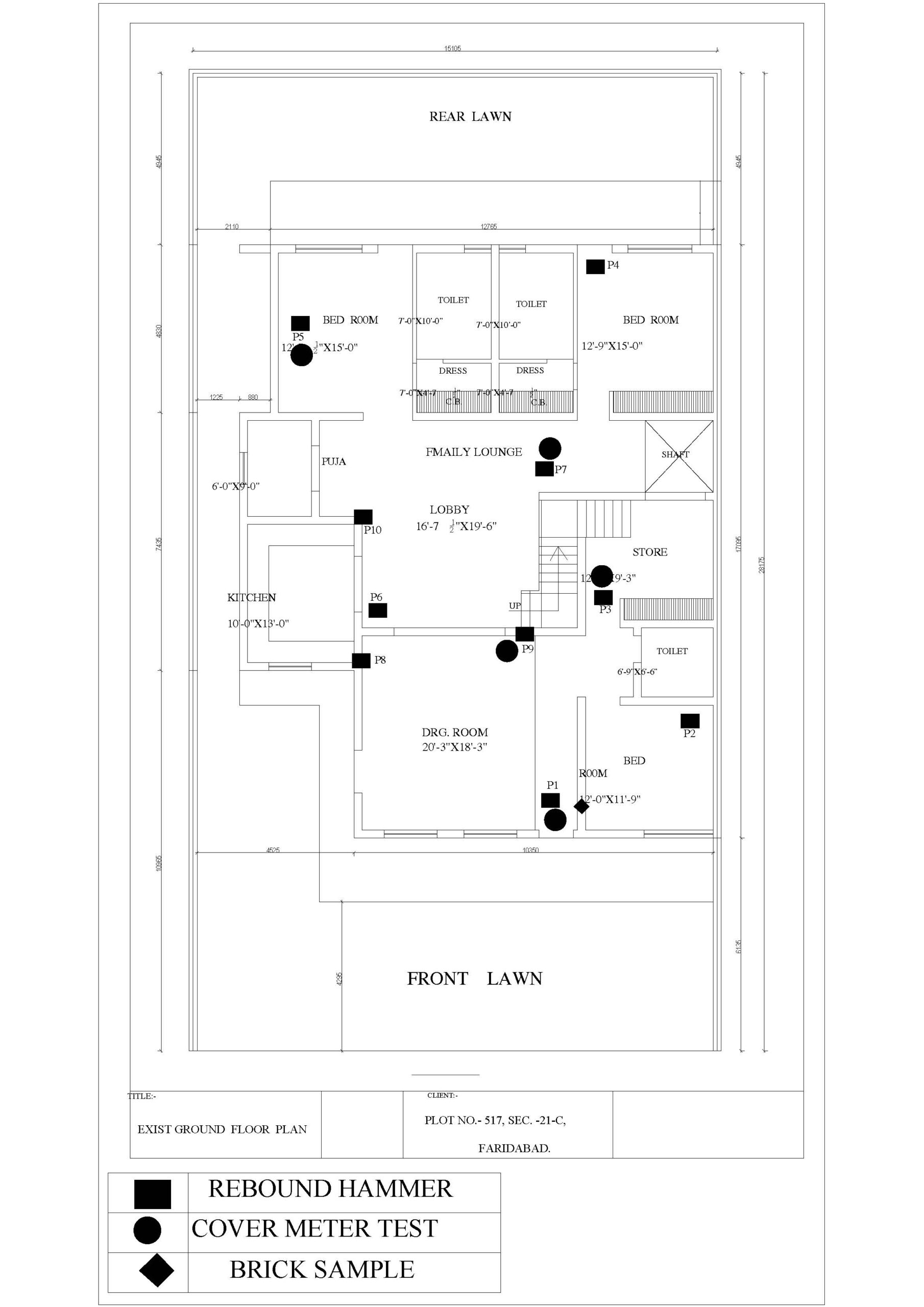
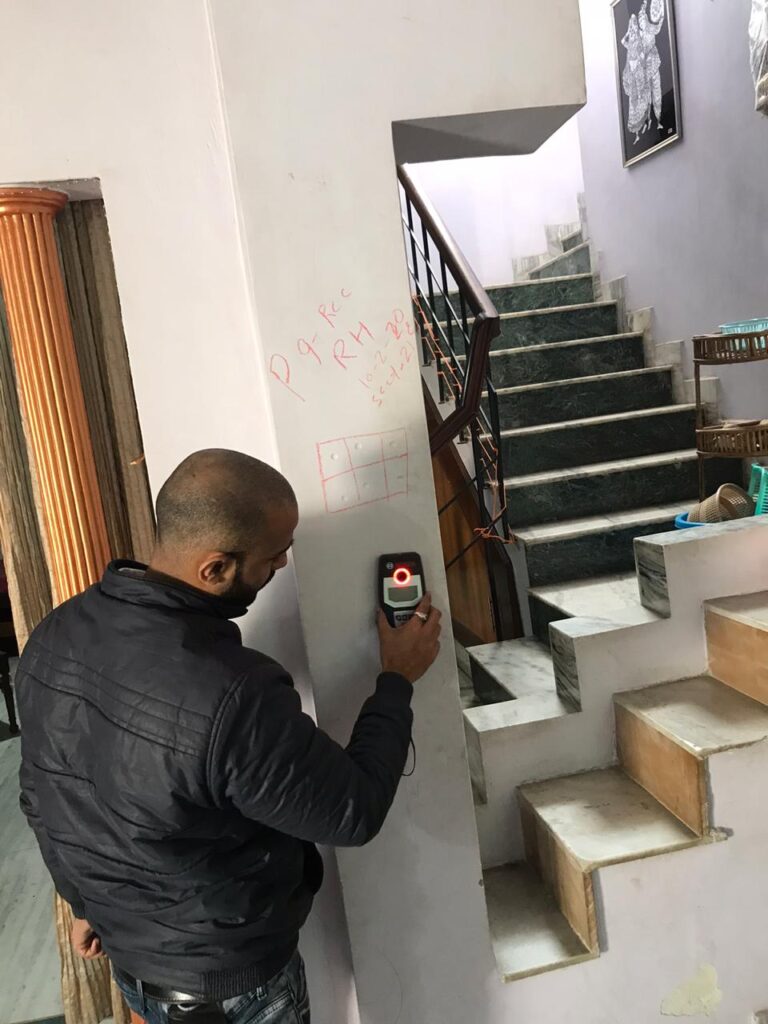
Testing photograph
rebound hammer

rcc scan
Relevant Testing Code-
Structure Adequacy Analysis
STRUCTURE ANALYSIS OF OLD BUILDING
AT
517, sectOR-21c faridabad haryana
for
M/s U.S Associate
1. Method of structural adequacy analysis and design parameters:-
The seismic safety of a reinforced concrete building will depend upon the initial architectural and structural configuration of the total building, the quality of the Structural analysis, design and reinforcement detailing of the building frame to achieve stability of elements and their ductile performance under severe seismic lading. Proper quality of construction and stability of the infill walls and partitions are additional safety requirements of the structure as a whole. Any weakness left in the structure, whether in design or in construction will be fully revealed during the postulated maximum considered earthquake for the seismic zone 4 in the earthquake code IS: 1893.
Assumptions in static analysis
The basic assumptions in static analysis methodology are as follows:-
- The behavior of the structure is assumed to be perfectly linear and deformations are small
- All joints are rigid
- The members are subjected to axial, flexural and shear deformations
- The force deformation relationship remains linear during the entire load regime.
- Plinth beams are assumed
Mathematical Modeling
The structure is idolized as a 3-D space frame model. The beams and columns are considered as members. The floor slab load is given on beam members. The brick wall is used as a filler wall and is not casted monolithically with structure; hence this load is also given on beam members. The columns are assumed to be fixed at the foundation level.
2. Loads for Superstructure and Sub structural elements:
- Grade of Concrete: M15 ( As per NDT Test )
- Steel: Fe415
- Slab thickness: 150mm
- Density of Concrete: 25kN/m³
- Density of Brick: 20kN/m³
- Ground floor to First floor level height = 3.40m
- Live load on other floors: 2.5kN/m²,
- Live load on roof : 1.5 kN/m²,
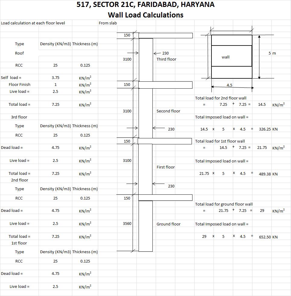
Dead Loads:3.75 kN/m²,
- Floor load: 4.75kN/m² (all dead load included in it like tiles, False ceiling and others)
- Top Floor load: 6.35kN/m² (all dead load included in it like top profile, False ceiling and others)
- Floor Wall Load: 15KN/M
- Terrace Parapet Wall Load: 3KN/M
3. Materials properties data for static analysis: (as given in test certificates of reports; clause no 4.1)
1) Concrete
a) Concrete grade : Grade of concrete: M 15
b) Static modulus of elasticity Ec : 5000√fck
c) Poisson’s ratio : 0.17
d) Unit weight of R.C.C : 25 kN/m3
e) P.C.C : nominal mix of 1:4:8
2) Reinforcement Steel
Yield strength Fy : 415 N/mm2
Conforming to IS 1786 -1985
Static modulus of elasticity Es : 2 x 10⁵ N/mm2
4. Load combinations
Combination of Loads considered in analysis: The structural design has been carried out in accordance with the provisions of the codes IS 456 – 2000 and IS 1893 – 2002 for Normal design conditions
Table of Load combinations and load factors as per (Ref. IS: 456 – 2000, CI.18.2.3.1, 36.4.1, and B4.3)
Note: DL = Dead Load, LL = Live Load/ Superimposed Load, WL = Wind Load, EL = Earthquake load
5.Summary of Structural adequacy
| Members | Limit State of Collapse (Normal) for Zone 4 |
| Slab Wall Column | All Slabs are safe for loading as per IS456:2000 and SP16 still steel beam are need to be proposed to control the deflection. All walls are safe for loading as per IS456,IS 1905, IS 875 and SP16 for ground+2 floors only. All column are safe for loading as per IS456:2000 and SP16 in dead and live load only. Unsafe in earthquake forces (column concrete grade is insufficient). |
*Recommandations :-
- For the floors more than G+2 there is need to increase the thickness of wall.
Or
The Framed structure need to be prepared from ground floor to top.
Or
The existing wall need to be strengthen with horizontal or vertical bands as per design neeeded.
SLAB ANALYSIS CALCULATION SHEET
WALL ANALYSIS CALCULATION SHEET
Leave a Reply